This thread has been locked.

If you have a related question, please click the "Ask a related question" button in the top right corner. The newly created question will be automatically linked to this question.

TMS320F28379D: TMS320F28379D: Missing pulses with variable phase-shift

Part Number: TMS320F28379D


Tool/software:

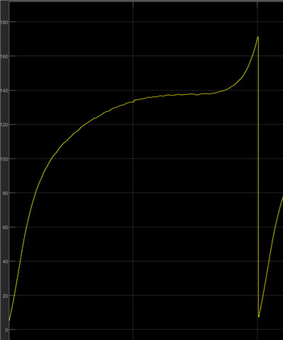
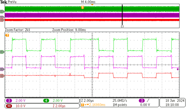
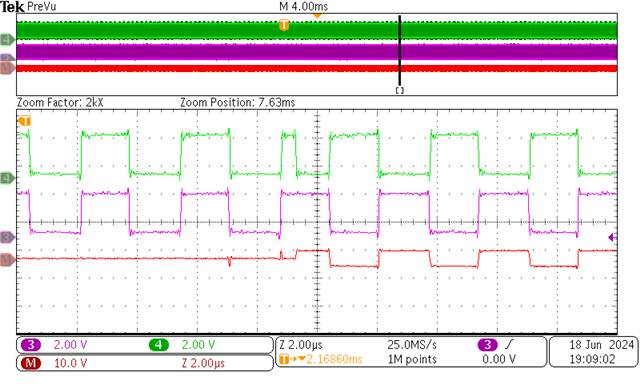
Hello I am doing dc-ac power conversion testing using this microcontroller. I am having issues with missing pulses. I am using four epwm outputs to control phase shift of four half-bridge legs. I do have a sharp transition in the phase shift values (from say -90 degree to 90 degree) near the zero crossing - which is where I am having issue. I compute the phase shift values using matlab and then use a lookup table to map them with the corresponding grid voltage. 

How can I resolve this issue?

Thank you in advance. 

  • Hello,

    Please take a look at MathWorks FAQ at this link below:

    If you have further questions, the best way to get support on MathWorks products is to contact MathWorks live tech support.

    You can also search for answers or post a question on MATLAB Answers C2000 forum. Additionally, there is info on MathWorks support C2000 in Documentation and Examples.

    I will close the thread from here as the software is supported by MathWorks team on their forum.

    Thanks

    Aswin

  • HI Aswin, 

    Thank you but the he issue I am facing is similar to what I would face if I programmed it on CCS.  Let me clarify a bit more. The problem I have in most cases is near zero crossing as the phase shift counter abruptly changes near the zero-crossing point of the grid voltage during each half line cycle. I have a condition which checks to make sure that TBPHS is TBPHS+1 when it exceeds the CMPA value (165). As shown here it can go slightly above 165.  Does this condition need to be checked when it goes near -165 as well? 

    As I mentioned earlier, I am using look ePWM 1-4 and loading the TBPHS values of these epwms from a look up table which stores the phase-shift values. The frequency is a fixed value. How do I ensure that a compare even is not missed during these abrupt transitions? 

    I am using shadow mode for epwm1 and immediate mode for the other three. The phase shifts are loaded on EPWM 2, 3 and 4. No phase shift is being loaded on epwm 1 as it is the zero reference point for each. 

  • Hi,

    Let me loop EPWM experts for further discussion.

    Thanks

    Aswin

  • Hi Firehiwot,

    Variable phase shift can sometimes cause action qualifiers to be skipped, depending the action qualifiers and TBPHS values used. I unfortunately cannot speak to your MATLAB code, but I have addressed this issue in past E2E threads with a workaround:

    https://e2e.ti.com/support/microcontrollers/c2000-microcontrollers-group/c2000/f/c2000-microcontrollers-forum/1312604/tms320f28379d-tms320f28379d-phase-shift-pwm-missing-pulse 

    Please let me know if I am misunderstanding the issue.

    Best Regards,

    Allison

  • Hi Allison, 

    Thank you. Yes I am having similar issue. I implemented the logic in simulink by comparing TBPHS and CMPA  and TBCTR and CMPA. I didn't know how to access TBCTR in Simulink so I used a counter from 0 to TBPRD (330). I am feeding this into the epwm block as an input for SWFSYNC. I am not sure if I am doing this correctly but I am now missing more pulses. In addition, this condition is not true for all epwm outputs that I have so could there be another way of handling this issue?

    Thank you. 

  • This is the waveform I have now using the approach I tried implementing based on your suggestion.

    Previous waveform has fewer missing pulses. 

  • Hi Allison, 

    would you suggest using a forced software input instead of trigger 1 for up count mode to prevent missing pulses? I was able to find this option in the epwm block in simulink. I saw in the datasheet that it has the highest priority of all action qualifier conditions. I still have issues with missing pulses with this condition triggering my epwm and they occur through out the negative phase shift range which I think occurs because I am adding 330 (TBPRD) to the negative phase shift values from my lookup table. (1) is the phase shift input. Do you have any suggestions on how to resolve this?

    Thank you in advance. 

  • Hi Firehiwot,

    Unfortunately I cannot help with the MATLAB - you will need to reach out via the resources Aswin listed above for specific help there; perhaps there may be a way to access TBCTR that I do not know of. In regards to the workaround, you would set the T1/T2 action qualifiers for whatever EPWM channel you are phase shifting and experiencing the issue with; it does not need to be configured for every PWM. 

    To implement the workaround, you should just need two have configurations that are dependent on your comparisons, and reconfigure (enable/disable) T1/T2 action qualifiers as a result. The T1/T2 actions should then occur when the sync pulse happens and thus perform any action that would normally be skipped over.

    I believe the software force might also work, but you can only specify one action as a result of the software force, so if you miss rising edges and falling edges due to syncs it would be more difficult to adjust for the different actions. I don't personally have familiarity with it used for this case specifically and historically suggest the T1/T2 method.

    Best Regards,

    Allison

  • Hello Allison, 

    Thank you. I have now shifted to CCS to program the microcontroller. I was able to resolve a case where TBPHS goes to much higher than CMPA using the approach you mentioned. I added an ISR like this and it helped get rid of the missing pulse in EPwm2. 

    void CheckAndSetEPWM2Action()
    {
        if ((EPwm2Regs.TBCTR < EPwm2Regs.CMPA.bit.CMPA) &&
                (EPwm2Regs.TBPHS.bit.TBPHS > EPwm2Regs.CMPA.bit.CMPA))
        {
            EALLOW;
            EPwm2Regs.AQCTLA.bit.PRD = AQ_SET; // Set PWM2A on period match
            EDIS;
        }
    
    }

    However, I also have a case where the phase shift changes from 0 up to CMPA or slightly higher (right now it exactly goes up to CMPA = 166). The missing pulses in the green waveforms occur around the area where I also had issues with EPWM2 which I resolved using the technique you suggested. 

    When I checked the value of TBCTR using the code below - it is higher than CMPA around 300 where my period is 333 and TBPHS either is close to CMPA or abruptly changes from near CMPA to a value slightly above zero (~20). How can I resolve this issue? As you can see, the missing pulse occurs when the phase shiftt between the green and purple waveforms shifts from 0 to 180 degree . 

    I also have tried two conditions to make sure I can clear but neither worked - the missing pulse occurs every 8.3ms which is the zero-crossing value of the voltage. 

        if (fabsf(rec_lead - rec_lead_prev) > 20) { // sharp transition

                 // Check if TBCTR is ahead of CMPA and rec_lead is less than or equal to duty_lead

            if (EPwm3Regs.TBCTR < EPwm3Regs.CMPA.bit.CMPA && EPwm3Regs.TBPHS.bit.TBPHS <= duty_lead){

                     // Adjust TBCTR to ensure it triggers just before CMPA

                     EPwm3Regs.TBCTR = EPwm3Regs.CMPA.bit.CMPA - 1;

                 }

             }

    Missing pulse 

    Phase shift 

  • Hi Firehiwot,

    Allison is out of office today, so please expect some delay in her response. 

    Best Regards,

    Delaney

  • Hi Delaney, 

    Is there any other person who could help if possible or would you recommend creating another post? I have a deadline so I need to get this to work. 

  • Part Number: TMS320F28379D

    Tool/software:

    Hello,
    I am trying to configure a one-shot load mode to avoid missing pulses as I have a sharp phase transition in phase from 0 to 180 degree and the value of my counter changes from near CMPA =166 to clos to zero. I am using the code below but the result I get is the same as what I had before. I am enabling one shot load mode on epwm2 and epwm3 with epwm 1 being the master. Is there anything I am doing wrong? I am computing the value of the phase shifts in the adc isr. 

    This is the missing pulse I have in epwm3 and epwm4 - I was able to resolve the missing pulse in epwm2 using the function below, however, the pulse in epwm3 and epwm4 is not resolved using this method. Will one shot load help? Can I use it on selected epwms instead of all epwms. I have the issue mainly in epwm3 and epwm4. 

    void CheckAndSetEPWM2Action()
    {
    if ((EPwm2Regs.TBCTR < EPwm2Regs.CMPA.bit.CMPA) &&
    (EPwm2Regs.TBPHS.bit.TBPHS > EPwm2Regs.CMPA.bit.CMPA))
    {
    EALLOW;
    EPwm2Regs.AQCTLA.bit.PRD = AQ_SET; // Set PWM2A on period match
    EDIS;
    }

    }

    void main(void)
    {
        //
        // Step 1. Initialize System Control:
        // PLL, WatchDog, enable Peripheral Clocks
        // This example function is found in the F2837xD_SysCtrl.c file.
        //
        InitSysCtrl();
    
        //
        // Step 2. Initialize GPIO:
        // This example function is found in the F2837xD_Gpio.c file and
        // illustrates how to set the GPIO to it's default state.
        //
        //InitGpio();
    
        //
        // Enable PWM1, PWM2 and PWM3
        //
        CpuSysRegs.PCLKCR2.bit.EPWM1=1;
        CpuSysRegs.PCLKCR2.bit.EPWM2=1;
        CpuSysRegs.PCLKCR2.bit.EPWM3=1;
        CpuSysRegs.PCLKCR2.bit.EPWM4=1;
        CpuSysRegs.PCLKCR2.bit.EPWM5=1;
    
        //
        // For this case just init GPIO pins for ePWM1, ePWM2, ePWM3
        // These functions are in the F2837xD_EPwm.c file
        //
        InitEPwmGpio();
        InitEPwm1Gpio();
        InitEPwm2Gpio();
        InitEPwm3Gpio();
        InitEPwm4Gpio();
        InitEPwm5Gpio();
        Gpio_setup1();
    
        //
        // Step 3. Clear all interrupts and initialize PIE vector table:
        // Disable CPU interrupts
        //
        DINT;
    
        //
        // Initialize the PIE control registers to their default state.
        // The default state is all PIE interrupts disabled and flags
        // are cleared.
        // This function is found in the F2837xD_PieCtrl.c file.
        //
        InitPieCtrl();
    
        //
        // Disable CPU interrupts and clear all CPU interrupt flags:
        //
        IER = 0x0000;
        IFR = 0x0000;
    
        //
        // Initialize the PIE vector table with pointers to the shell Interrupt
        // Service Routines (ISR).
        // This will populate the entire table, even if the interrupt
        // is not used in this example.  This is useful for debug purposes.
        // The shell ISR routines are found in F2837xD_DefaultIsr.c.
        // This function is found in F2837xD_PieVect.c.
        //
        InitPieVectTable();
    
        // Interrupts that are used in this example are re-mapped to
        // ISR functions found within this file.
        //
        EALLOW; // This is needed to write to EALLOW protected registers
        PieVectTable.ADCA1_INT = &adca1_isr;
        EDIS;   // This is needed to disable write to EALLOW protected registers
    
        ConfigureADC();
    
        //
        // For this example, only initialize the ePWM
        //
        EALLOW;
        CpuSysRegs.PCLKCR0.bit.TBCLKSYNC = 0;
        //ClkCfgRegs.PERCLKDIVSEL.bit.EPWMCLKDIV=0; // added to make sure that the epwmclk =sysclk/1 or 200MHz otherwise it's 100MHz
        EDIS;
    
        InitEPwm1Example();
        InitEPwm2Example();
        InitEPwm3Example();
        InitEPwm4Example();
        InitEPwm5Example();
    
        EALLOW;
        CpuSysRegs.PCLKCR0.bit.TBCLKSYNC = 1; // 100 MHz clock frequency
        EDIS;
    
    
        SetupADCEpwm();
        
        // Sync source ePWM1 settings
        EPwm1Regs.GLDCFG.bit.CMPA_CMPAHR = 1;
        EPwm1Regs.GLDCFG.bit.TBPRD_TBPRDHR = 1;
        EPwm1Regs.GLDCFG.bit.DBRED_DBREDHR = 1;
        EPwm1Regs.GLDCFG.bit.DBFED_DBFEDHR = 1;
        EPwm1Regs.GLDCFG.bit.CMPC = 1;
        EPwm1Regs.GLDCTL.bit.GLD = 1;
        EPwm1Regs.GLDCTL.bit.GLDMODE = 0; // counter =0;
        EPwm1Regs.GLDCTL.bit.OSHTMODE = 1;
        EPwm1Regs.GLDCTL.bit.GLD = 1;
    
        // Sync receiver ePWM3 settings
        EPwm3Regs.GLDCFG.bit.CMPA_CMPAHR = 1;
        EPwm3Regs.GLDCFG.bit.TBPRD_TBPRDHR = 1;
        EPwm3Regs.GLDCFG.bit.DBRED_DBREDHR = 1;
        EPwm3Regs.GLDCFG.bit.DBFED_DBFEDHR = 1;
        EPwm3Regs.GLDCTL.bit.GLD = 1;
        EPwm3Regs.GLDCTL.bit.GLDMODE = 2; // Synchronization event;
        EPwm3Regs.GLDCTL.bit.OSHTMODE = 1;
        EPwm3Regs.GLDCTL.bit.GLD = 1;
    
        EPwm2Regs.GLDCFG.bit.CMPA_CMPAHR = 1;
        EPwm2Regs.GLDCFG.bit.TBPRD_TBPRDHR = 1;
        EPwm2Regs.GLDCFG.bit.DBRED_DBREDHR = 1;
        EPwm2Regs.GLDCFG.bit.DBFED_DBFEDHR = 1;
        EPwm2Regs.GLDCTL.bit.GLD = 1;
        EPwm2Regs.GLDCTL.bit.GLDMODE = 2; // Synchronization event;
        EPwm2Regs.GLDCTL.bit.OSHTMODE = 1;
        EPwm2Regs.GLDCTL.bit.GLD = 1;
    
        // Link the GLDCTL2 register of ePWM2 to ePWM1
        EPwm3Regs.EPWMXLINK.bit.GLDCTL2LINK = 28;//EPWM_LINK_WITH_EPWM_1;
        EPwm2Regs.EPWMXLINK.bit.GLDCTL2LINK = 29;//EPWM_LINK_WITH_EPWM_1;
    
        //
        // Step 4. User specific code, enable interrupts:
        //
        // Enable CPU INT1 which is connected to adc int1:
        //
    
        PieCtrlRegs.PIEIER1.bit.INTx1 = 1; // enable epwm interrupt
    
        IER |= M_INT1;
    
        //
        // Enable global Interrupts and higher priority real-time debug events:
        //
        EINT;  // Enable Global interrupt INTM
        ERTM;  // Enable Global realtime interrupt DBGM
    
        // Step 5. IDLE loop. Just sit and loop forever (optional):
        //
    
        for(;;)
    
        {
            asm ("  NOP");
        }
    
    }


    interrupt void adca1_isr(void)
    {
    
        duty_inv=duty50;
        duty_lead=duty50;
        duty_lag=duty50;
    
        // for the math function use f at the end (floating point calculation) to ensure that the computation doesn't take too long
    
        Vgrid=Vpk*sinf(Omega*count*tsample); // sample_period = n*1/fs;
        absVgrid=fabsf(Vgrid);
        vr=absVgrid/Vpk;
    
        dv=absVgrid-fabsf(Vprev); // double check on this
    
        if(dv>=0){
            z = (vr * cosf(theta) - sinf(theta) * sqrtf(1 - vr*vr)) / vr;
    
        }
    
        else if(dv<0){
            z = (vr * cosf(theta) + sinf(theta) * sqrtf(1 - vr*vr)) / vr;
    
        }
    
        delta=atanf(term2*z);
        Phi=2*asinf(term1*vr*sqrtf(1+term2*term2));
    
        if(delta>1.57) // pi/2
            delta=1.57;
        if(Phi>3.14) // pi
            Phi=3.14;
    
        halfPhi = (int)(0.5*Phi*angle_factor);
        twodelta = (int)(2 * delta * angle_factor);
        halfInv  = (int) (0.5 * twodelta);
    
        rec_lead = (int)(halfInv + 83 - halfPhi); // leading leg phase
        rec_lag  = (int)(halfInv + 83 + halfPhi); // lagging leg phase
    
        // make negative angles positive by adding one period
    
        if (twodelta < 0)
            twodelta += switching_period;
        if (rec_lead < 0)
            rec_lead += switching_period;
        if (rec_lag < 0)
            rec_lag += switching_period;
    
        if(twodelta>duty50 && twodelta_prev<=duty50){ // remove missing pulse around CMPA for inverter - long high signal - missing CMPA
            duty_inv=twodelta+1;
        }
    
        if(rec_lead>duty50 && rec_lead_prev<=duty50) // remove missing pulse around CMPA for inverter
            duty_lead=rec_lead+1;
    
        if(rec_lag>duty50 && rec_lag_prev<=duty50) // remove missing pulse around CMPA for inverter
            duty_lag=rec_lag+1;
    
        EPwm2Regs.CMPA.bit.CMPA = duty_inv;  // Set compare A value
        EPwm2Regs.TBPHS.bit.TBPHS = twodelta; // Rectifier leading leg  phase
    
        EPwm3Regs.CMPA.bit.CMPA = duty_lead;
        EPwm3Regs.TBPHS.bit.TBPHS = rec_lead;
    
    
        EPwm4Regs.CMPA.bit.CMPA = duty_lag;  // Set compare A value
        EPwm4Regs.TBPHS.bit.TBPHS = rec_lag; // Rectifier lagging leg phase
    
    
        count=count+1;
        if (count>count_max)
            count=0.000; // used to ensure that z is computed when count~0
    
        Vprev=Vgrid;
        twodelta_prev=twodelta;
        delta_prev=delta;
        rec_lag_prev=rec_lag;
        rec_lead_prev=rec_lead;
        
        EPwm1Regs.GLDCTL2.bit.OSHTLD = 1;
    
        AdcaRegs.ADCINTFLGCLR.bit.ADCINT1 = 1; //clear INT1 flag
        PieCtrlRegs.PIEACK.all = PIEACK_GROUP1;
    }
    
    //
    // InitEPwm1Example - Initialize EPWM1 values
    //
    void InitEPwm1Example()
    {
    
        //
        // Setup TBCLK
        //
        EPwm1Regs.TBCTL.bit.CTRMODE = TB_COUNT_UP; // Count up
        EPwm1Regs.TBPRD = switching_period-1;       // Set timer period
        EPwm1Regs.TBCTL.bit.PHSEN = TB_DISABLE;    // Disable phase loading
        EPwm1Regs.TBPHS.bit.TBPHS = 0x0000;        // Phase is 0
        EPwm1Regs.TBCTL.bit.SYNCOSEL = TB_CTR_ZERO; // Sync down stream module
        EPwm1Regs.TBCTR = 0x0000;                  // Clear counter
        EPwm1Regs.TBCTL.bit.HSPCLKDIV = TB_DIV1;   // Clock ratio to SYSCLKOUT
        EPwm1Regs.TBCTL.bit.CLKDIV = TB_DIV1;
    
        //
        // Setup shadow register load on ZERO
        //
        EPwm1Regs.CMPCTL.bit.SHDWAMODE = CC_SHADOW;
        EPwm1Regs.CMPCTL.bit.SHDWBMODE = CC_SHADOW;
        EPwm1Regs.CMPCTL.bit.LOADAMODE = CC_CTR_ZERO;
        EPwm1Regs.CMPCTL.bit.LOADBMODE = CC_CTR_ZERO;
    
        //
        // Set Compare values
        //
        EPwm1Regs.CMPA.bit.CMPA = duty50;     // Set compare A value
        EPwm1Regs.CMPB.bit.CMPB = duty50;     // Set Compare B value
    
        //
        // Set actions
        //
        EPwm1Regs.AQCTLA.bit.ZRO = AQ_SET;            // Set PWM1A on Zero
        EPwm1Regs.AQCTLA.bit.CAU = AQ_CLEAR;          // Clear PWM1A on event A,
    
        // up count
    
        //
        // Set dead band
        //
        EPwm1Regs.DBCTL.bit.OUT_MODE = DB_FULL_ENABLE; // enable Dead-band module
        EPwm1Regs.DBCTL.bit.POLSEL = DB_ACTV_HIC; // Active Hi complementary
        EPwm1Regs.DBCTL.bit.IN_MODE = DBA_ALL;
        EPwm1Regs.DBCTL.bit.HALFCYCLE = 1;
        EPwm1Regs.DBRED.bit.DBRED = 10;
        EPwm1Regs.DBFED.bit.DBFED = 10;
    
        // Configure ePWM1 to one-shot load mode
        //
        EPwm1Regs.ETSEL.bit.SOCAEN = 1;        // Enable SOCA
        EPwm1Regs.ETSEL.bit.SOCASEL = ET_CTR_ZERO; // Trigger on counter zero
        EPwm1Regs.ETPS.bit.SOCAPRD = ET_1ST;   // Generate pulse on 1st event
    
        EPwm1Regs.ETSEL.bit.INTEN = 1;         // Enable interrupt on SOCA
        EPwm1Regs.ETSEL.bit.INTSEL = ET_CTR_ZERO; // Interrupt on counter zero
        EPwm1Regs.ETPS.bit.INTPRD = ET_1ST;    // Generate interrupt on 1st event
    
    }
    
    //
    // InitEPwm2Example - Initialize EPWM2 values
    //
    void InitEPwm2Example()
    {
    
        //
        // Setup TBCLK
        //
        EPwm2Regs.TBCTL.bit.CTRMODE = TB_COUNT_UP; // Count up
        EPwm2Regs.TBPRD = switching_period-1;       // Set timer period
        EPwm2Regs.TBCTL.bit.PHSEN = TB_ENABLE;    // Disable phase loading
        EPwm2Regs.TBPHS.bit.TBPHS =switching_period-31;    // Phase is 0
        EPwm2Regs.TBCTL.bit.SYNCOSEL = TB_SYNC_IN;//TB_SYNC_IN; // Sync down stream module
        EPwm2Regs.TBCTR = 0x0000;                  // Clear counter
        EPwm2Regs.TBCTL.bit.HSPCLKDIV = TB_DIV1;   // Clock ratio to SYSCLKOUT
        EPwm2Regs.TBCTL.bit.CLKDIV = TB_DIV1;
    
        //
        // Setup shadow register load on ZERO
        //
        EPwm2Regs.CMPCTL.bit.SHDWAMODE = CC_SHADOW;
        EPwm2Regs.CMPCTL.bit.SHDWBMODE = CC_SHADOW;
        EPwm2Regs.CMPCTL.bit.LOADAMODE = CC_CTR_ZERO;
        EPwm2Regs.CMPCTL.bit.LOADBMODE = CC_CTR_ZERO;
    
        //
        // Set Compare values
        //
        EPwm2Regs.CMPA.bit.CMPA =  duty50;      // Set compare A value
        EPwm2Regs.CMPB.bit.CMPB =  duty50;      // Set Compare B value
    
        //
        // Set actions
        //
        EPwm2Regs.AQCTLA.bit.ZRO = AQ_SET;            // Set PWM2A on Zero
        EPwm2Regs.AQCTLA.bit.CAU = AQ_CLEAR;          // Clear PWM2A on event A,
    
        // up count
    
        //
        // Set dead band
        //
        EPwm2Regs.DBCTL.bit.OUT_MODE = DB_FULL_ENABLE; // enable Dead-band module
        EPwm2Regs.DBCTL.bit.POLSEL = DB_ACTV_HIC; // Active Hi complementary
        EPwm2Regs.DBCTL.bit.IN_MODE = DBA_ALL;
        EPwm2Regs.DBCTL.bit.HALFCYCLE = 1;
        EPwm2Regs.DBRED.bit.DBRED = 10;
        EPwm2Regs.DBFED.bit.DBFED = 10;
    
        // Configure ePWM3 to one-shot load mode
        //
        EPwm2Regs.ETSEL.bit.SOCAEN = 1;        // Enable SOCA
        EPwm2Regs.ETSEL.bit.SOCASEL = ET_CTR_ZERO; // Trigger on counter zero
        EPwm2Regs.ETPS.bit.SOCAPRD = ET_1ST;   // Generate pulse on 1st event
    
        EPwm2Regs.ETSEL.bit.INTEN = 1;         // Enable interrupt on SOCA
        EPwm2Regs.ETSEL.bit.INTSEL = ET_CTR_ZERO; // Interrupt on counter zero
        EPwm2Regs.ETPS.bit.INTPRD = ET_1ST;    // Generate interrupt on 1st event
    
    }
    
    //
    // InitEPwm3Example - Initialize EPWM3 values
    //
    void InitEPwm3Example(void)
    {
        //
        // Setup TBCLK
        //
        EPwm3Regs.TBCTL.bit.CTRMODE = TB_COUNT_UP; // Count up
        EPwm3Regs.TBPRD = switching_period-1;       // Set timer period
        EPwm3Regs.TBCTL.bit.PHSEN = TB_ENABLE;    // Disable phase loading
        EPwm3Regs.TBPHS.bit.TBPHS = 50;        // Phase is 0
        EPwm3Regs.TBCTL.bit.SYNCOSEL = TB_SYNC_IN; // Sync down stream module
        EPwm3Regs.TBCTR = 0x0000;                  // Clear counter
        EPwm3Regs.TBCTL.bit.HSPCLKDIV = TB_DIV1;   // Clock ratio to SYSCLKOUT
        EPwm3Regs.TBCTL.bit.CLKDIV = TB_DIV1;
    
        //
        // Setup shadow register load on ZERO
        //
        EPwm3Regs.CMPCTL.bit.SHDWAMODE = CC_SHADOW;
        EPwm3Regs.CMPCTL.bit.SHDWBMODE = CC_SHADOW;
        EPwm3Regs.CMPCTL.bit.LOADAMODE = CC_CTR_ZERO;
        EPwm3Regs.CMPCTL.bit.LOADBMODE = CC_CTR_ZERO;
    
        //
        // Set Compare values
        //
        EPwm3Regs.CMPA.bit.CMPA = duty50;  // Set compare A value
        EPwm3Regs.CMPB.bit.CMPB = duty50;  // Set Compare B value
    
    
        //
        // Set Actions
        //
        EPwm3Regs.AQCTLA.bit.ZRO = AQ_SET;            // Set PWM3A on Zero
        EPwm3Regs.AQCTLA.bit.CAU = AQ_CLEAR;          // Clear PWM3A on event A,
        // up count
    
        //
        // Set dead band
        //
        EPwm3Regs.DBCTL.bit.OUT_MODE = DB_FULL_ENABLE; // enable Dead-band module
        EPwm3Regs.DBCTL.bit.POLSEL = DB_ACTV_HIC; // Active Hi complementary
        EPwm3Regs.DBCTL.bit.IN_MODE = DBA_ALL;
        EPwm3Regs.DBCTL.bit.HALFCYCLE = 1;
        EPwm3Regs.DBRED.bit.DBRED = 10;
        EPwm3Regs.DBFED.bit.DBFED = 10;
    
        // Configure ePWM3 to one-shot load mode
        //
        EPwm3Regs.ETSEL.bit.SOCAEN = 1;        // Enable SOCA
        EPwm3Regs.ETSEL.bit.SOCASEL = ET_CTR_ZERO; // Trigger on counter zero
        EPwm3Regs.ETPS.bit.SOCAPRD = ET_1ST;   // Generate pulse on 1st event
    
        EPwm3Regs.ETSEL.bit.INTEN = 1;         // Enable interrupt on SOCA
        EPwm3Regs.ETSEL.bit.INTSEL = ET_CTR_ZERO; // Interrupt on counter zero
        EPwm3Regs.ETPS.bit.INTPRD = ET_1ST;    // Generate interrupt on 1st event
    
    
    }
    
    //
    // InitEPwm4Example - Initialize EPWM4 values
    //
    void InitEPwm4Example(void)
    { //
        // Setup TBCLK
        //
        EPwm4Regs.TBCTL.bit.CTRMODE = TB_COUNT_UP; // Count up
        EPwm4Regs.TBPRD = switching_period-1;       // Set timer period
        EPwm4Regs.TBCTL.bit.PHSEN = TB_ENABLE;    // Disable phase loading
        EPwm4Regs.TBPHS.bit.TBPHS = 50;        // Phase is 0
        EPwm4Regs.TBCTL.bit.SYNCOSEL = TB_SYNC_IN; // Sync down stream module
        EPwm4Regs.TBCTR = 0x0000;                  // Clear counter
        EPwm4Regs.TBCTL.bit.HSPCLKDIV = TB_DIV1;   // Clock ratio to SYSCLKOUT
        EPwm4Regs.TBCTL.bit.CLKDIV = TB_DIV1;
    
        //
        // Setup shadow register load on ZERO
        //
        EPwm4Regs.CMPCTL.bit.SHDWAMODE = CC_IMMEDIATE;
        EPwm4Regs.CMPCTL.bit.SHDWBMODE = CC_IMMEDIATE;
        EPwm4Regs.CMPCTL.bit.LOADAMODE = CC_CTR_ZERO_PRD;
        EPwm4Regs.CMPCTL.bit.LOADBMODE = CC_CTR_ZERO_PRD;
    
        // Set Compare values
        //
        EPwm4Regs.CMPA.bit.CMPA = duty50;  // Set compare A value
        EPwm4Regs.CMPB.bit.CMPB = duty50;  // Set Compare B value
    
        //
        // Set Actions
        //
        EPwm4Regs.AQCTLA.bit.ZRO = AQ_SET;            // Set PWM3A on Zero
        EPwm4Regs.AQCTLA.bit.CAU = AQ_CLEAR;          // Clear PWM3A on event A,
        // up count
        // Set dead band
        //
        EPwm4Regs.DBCTL.bit.OUT_MODE = DB_FULL_ENABLE; // enable Dead-band module
        EPwm4Regs.DBCTL.bit.POLSEL = DB_ACTV_HIC; // Active Hi complementary
        EPwm4Regs.DBCTL.bit.IN_MODE = DBA_ALL;
        EPwm4Regs.DBCTL.bit.HALFCYCLE = 1;
        EPwm4Regs.DBRED.bit.DBRED = 10;
        EPwm4Regs.DBFED.bit.DBFED = 10;
    }
    
    
    void Gpio_setup1(void)
    {
        //
        // Enable an GPIO output on GPIO6, set it high
    
        EALLOW;
    
        GpioCtrlRegs.GPBMUX2.bit.GPIO48 = 0;  // GPIO6 = GPIO6
        GpioCtrlRegs.GPBDIR.bit.GPIO48 = 1;   // GPIO6 = output
    
        GpioCtrlRegs.GPBMUX2.bit.GPIO49 = 0;  // GPIO6 = GPIO6
        GpioCtrlRegs.GPBDIR.bit.GPIO49= 1;   // GPIO6 = output
    
        GpioCtrlRegs.GPBMUX2.bit.GPIO50 = 0;  // GPIO6 = GPIO6
        GpioCtrlRegs.GPBDIR.bit.GPIO50 = 1;   // GPIO6 = output
    
        GpioCtrlRegs.GPBMUX2.bit.GPIO51 = 0;  // GPIO6 = GPIO6
        GpioCtrlRegs.GPBDIR.bit.GPIO51 = 1;   // GPIO6 = output
    
        EDIS;
    
    }
    
    void InitEPwm5Example(void)
    {
    
        EPwm5Regs.TBPRD = sample_period-1;       // Set timer period
        EPwm5Regs.TBCTL.bit.CTRMODE = TB_COUNT_UP; // Count up
        EPwm5Regs.TBCTL.bit.PRDLD = TB_SHADOW; // Enable shadow mode
        EPwm5Regs.TBCTL.bit.HSPCLKDIV = TB_DIV1;   // Clock ratio to SYSCLKOUT
        EPwm5Regs.TBCTL.bit.CLKDIV = TB_DIV1;
    
        EPwm5Regs.ETSEL.bit.SOCAEN     = 1;        // Enable SOC on A group
        EPwm5Regs.ETSEL.bit.SOCASEL    = 1;        // Select SOC from CPMB while incrementing
        EPwm5Regs.ETPS.bit.SOCAPRD     = 1;        // Generate pulse on 1st event
    
        EPwm5Regs.CMPA.bit.CMPA = sample_period/2;    // Set compare A value
    
    }


    Thank you. 

  • Hi Firehiwot,

    Allison will have a response back to you tomorrow, I'm sorry for the delay. Thank you for your patience.

    Best Regards,

    Delaney

  • Hi Firehiwot,

    Sorry for the delay as I was out of office. I wanted to reiterate that if the issue is missing action qualifiers due to syncing/phase shift, the working solution I suggested is to utilize T1 and T2 action qualifiers to perform the missed actions. For example, since a sync pulse is the time of a missed action, you would use the EPWMxSYNC signal as the T1/T2 event sources and then set the action taken on T1 (when counting in a specific direction) to be setting the EPWM high or low depending on the case (same for T2). In this way, the action from a T1 or T2 event would supplement what the missing actions would have done:

    https://e2e.ti.com/support/microcontrollers/c2000-microcontrollers-group/c2000/f/c2000-microcontrollers-forum/1312604/tms320f28379d-tms320f28379d-phase-shift-pwm-missing-pulse 

    Best Regards,

    Allison

  • Hi Allison, 

    Thank you very much. Am I doing the T1 event correctly? The code below is what I used for EPWM2 and it worked but  I tried doing the same on EPWM3 and it is not working. Could you give me an example of how I should use T1 ( I am using only up count mode). Is this the correct way of doing it? The second link you shared is also not working. Could you please share the correct link. 

    void CheckAndSetEPWM2Action()
    {
    if ((EPwm2Regs.TBCTR < EPwm2Regs.CMPA.bit.CMPA) &&
    (EPwm2Regs.TBPHS.bit.TBPHS > EPwm2Regs.CMPA.bit.CMPA))
    {
    EALLOW;
    EPwm2Regs.AQCTLA.bit.PRD = AQ_SET; // Set PWM2A on period match
    EDIS;
    }

    }

    I am specifically haivng issue when transitioning form a phase shift near CMPA t(166) to close to zero. I tried both shadow and immediate modes and neither seem to work. Could you please take a look at my epwm configuration for epwm3 and 4. Not sure how to resolve this. 

    Thank you. 

  • Hi Firehiwot,

    Apologies the second link was a mistake - will omit it now.

    You will need to set up checks for the specific cases where you miss an action qualifier. This depends again on your action qualifiers. For example, if I am in up-count and have actions:

    • Set high on CMPA-up
    • Clear low on CMPB-up

    Then one case of missing action qualifier could be that CTR < CMPA and TBPHS > CMPA. In this case, the sync pulse will cause the counter to jump over CMPA and miss the action. So you need to check if CTR < CMPA and TBPHS > CMPA. If this condition is true, enable the T1 action qualifier where it uses the sync pulse to set the PWM high in place of where the CMPA-up action would have set the EPWM high, such as:

    EPWM_setActionQualifierT1TriggerSource(myEPWM1_BASE, EPWM_AQ_TRIGGER_EVENT_TRIG_EPWM_SYNCIN);   
    EPWM_setActionQualifierAction(myEPWM1_BASE, EPWM_AQ_OUTPUT_A, EPWM_AQ_OUTPUT_HIGH, EPWM_AQ_OUTPUT_ON_T1_COUNT_UP);  
    The same could be true for jumping over CMPB-up, but in that case, you would need the action to be setting the output LOW so that it replaces the missing "clear low" action on CMPB.  You should be using immediate load mode for the action qualifiers for this as you want it to change as soon as possible.

    Best Regards,

    Allison

  • Hi Allison, 

    Thank you, I have to test tomorrow but I was able to avoid the missing pulse for a portion of the cycle. The main issue I was having was that TBPHS is not exceeding CMPA. This is a very specific case for my application I think as it sharply changes from near 166 to near zero both of which are less than CMPA. Once I narrowed down the portion of the pwm signal with I was able to use the action qualifier trigger that you suggested and I also made sure that TBCTR is one less than CMPA to ensure that I have a clear action qualifier. Thank you for your help. 

    if(portion of missing pulse){ 

    EPwmxRegs.CMPA.bit.CMPA=duty;
    EPwmxRegs.TBCTR=duty-1; // need to make sure we can turn it off
    EPwmxRegs.AQCTLA2.bit.T1U = AQ_SET;
    }
    else{
    EPwm3Regs.AQCTLA2.bit.T1U = AQ_NO_ACTION;
    EPwm4Regs.AQCTLA2.bit.T1U = AQ_NO_ACTION;

    }

    Before using action qualifier and tbctr

    Only using TBCTR

    Using both TBCTR and action qualifier