This thread has been locked.

If you have a related question, please click the "Ask a related question" button in the top right corner. The newly created question will be automatically linked to this question.

TMDSCNCD28P65X: TMDSCNCD28P65X

Part Number: TMDSCNCD28P65X
Other Parts Discussed in Thread: C2000WARE, SYSCONFIG

Tool/software:

Hello there,

Is there a document or other reference to explain how the GPIO pins are mapped?

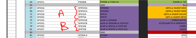
I have SPIA module setup to control me device A, and the default pins on Docking Station Board are 

SPISIMOA - 67
SPISOMIA - 69
SPICLKA - 71
SPISTEA - 73

All works so far!

Now I created SPIB wanting to control device B by MCU board. What the pins that should output SPIB signals on the Docking Station?

How to configure and how the pin numbers on the board drawing corresponds to GPIOxxx definitions in the header files?

Is there a way to map SPIA outputs to different pins on the board? What is the process?

I am new to MCU programming, so give as much details as possible, so I can follow and succeed with my project.

Thanks, Sergey.

  • Hi Sergey,

    Please refer the pinout for TMDSCNCD28P65X EVM.  pinout_p65x

    You should already have access to both SPI-A and SPI-B pins on the controlcard at these location. Ideal way is to use the SPI functionality at these specified pins, if you are using controlcard for your application. 


    Otherwise, you need to route those SPI pins to another GPIO locations, but we need to check if those pins are available over XBAR which is little complex. 

    Also, you can refer to below examples on how to configure those SPI and its usecase C:\ti\c2000\C2000Ware_5_02_00_00\driverlib\f28p65x\examples\c28x\spi

    Best Regards,

    Uttam Reddy

  • Thanks Uttam

    That document solved most of the problems, wish I could find it sooner!

    Now, I have hooked up all the wires, capture the signals, etc.

    But still have another problem with SPIB, 

    I have expanded or based my project on spi_ex7_eeprom_dma project.

    I have to add another SPI controller (SPIB)  to control two devices hooked up to the board.

    The problem is that SPIB does not trigger DMA interrupts to move on with the SPI transactions.

    Is there any differences in SPIB settings parameters or in DMA settings parameters to trigger the interrupts?

    Please look at the above project and help me to setup for SPIB to get it running.

    Regards,

    Sergey.

  • Hi Sergey, our DMA expert is out of office, you should hear back from them in a couple days.

  • Hi Sergey,

    I apologize for the delay. 

    In order to use SPI/DMA functionality with SPIB there shouldn't be any major differences. You should just need to use two other DMA channels (for example if SPIA TX is DMA CH1 and SPIA RX is DMA CH2, you could use DMA CH3 and CH4 for SPIB TX and SPIB RX) and change the DMA trigger source to use the SPIB triggers instead.

    Did you set up DMA interrupts for the 2 new DMA channels being used? Or are you referring to SPIB interrupts? Usually implementing DMA with SPI should eliminate the need to include SPIB interrupts. Can you also verify with a scope that no TX signal is being sent and that you are seeing the RX signal coming in correctly from the other device?

    Best Regards,

    Delaney

  • Thanks Delaney!

    I setup the project very much as you suggested for DMA channels, etc. 

    The only thing I was missing is to use DMA_TRIGGER_SPIBRX for SPIB.

    Now it all works!

    I have a couple of additional questions.

    1. Is it possible to run SPIA and SPIB in parallel, at the same time?

    When I trigger both to run, on the scope I see signals coming sequentially, SPIA first, then SPIB.

    We would have to use more SPI interfaces soon (SPIC, SPID), maybe up to 4, and EthrCAT on the same MCU.

    2. What would be the SPI C, D, pins on Docking Station, how to configure the additional SPI interfaces?  

    3. How to configure and what is mapping to Docking Station of the additional GPIO pins?

    All PWMxA, PWMxB are already used.

    Regards,

    Sergey.

  • Hi Sergey,

    Below are the answers to your questions:

    1. The DMA itself cannot run two channels at once; it uses an arbitration scheme to decide the order of channels to service. This should be why you are seeing this sequential behavior. There are two options for the arbitration scheme, a round robin mode where each channel has equal priority and is serviced one at a time, and a channel 1 priority mode where DMA CH1 is always serviced first. If you wanted to use SPI with DMA truly in parallel, you'd have to configure one instance on CPU1 and the other CPU2, since they have separate DMA modules. Another note: there are only 6 DMA channels for each CPU's DMA module, so the CPU1 DMA would only be able to interface with up to three different SPI channels (if using one channel for TX and one for RX for each SPI).

    2 & 3: I would suggest using the pinmux tool in Sysconfig to figure out which GPIOs are available to be used on the F28P65x controlCARD. You can set the board to the controlCARD and choose GPIOs for each SPI module that say (Header) to ensure they are pinned out on the docking station. You can add the ePWM instances and GPIOs there as well, and if there are any conflicts between a pin being used by more than one peripheral or peripheral instance, Sysconfig will throw an error.

    Best Regards,

    Delaney