This thread has been locked.

If you have a related question, please click the "Ask a related question" button in the top right corner. The newly created question will be automatically linked to this question.

TMS320F28388D: About Normal 1MHz, Data 4MHz communication in CAN-FD

Part Number: TMS320F28388D
Other Parts Discussed in Thread: TMDSCNCD28388D, C2000WARE

Tool/software:

Hi experts,

My customer is using F28388D (TMDSCNCD28388D) for evaluation, and I would like to confirm some things about Normal 1MHz, Data 4MHz communication in CAN-FD.

Q1: Are the following register settings no problem?

    bitTimingParams.dataRatePrescalar  = 0x0U; // Data Baud Rate Pre-scaler.
    bitTimingParams.dataTimeSeg1 = 0x7U; // Data Time segment before SP
    bitTimingParams.dataTimeSeg2 = 0x0U; // Data Time segment after SP
    bitTimingParams.dataSynchJumpWidth = 0x0U; // Data SJW

Q2: Is 5MHz the maximum bit rate for the Data section for CAN-FD?
Currently, they are using 40MHz, which is System 200MHz divided by 5.
The maximum frequency does not seem to be defined in the data sheet or TRM.

[Details]
The CAN communication pin of the TMDSCNCD28388D is connected to a CAN transceiver, and the CanBus is not connected to any other devices, only a termination resistor.
The CanBus CANH signal is observed with an oscilloscope.

The values ​​set with reference to the sample code "mcan_ex9_transmit.c" in C2000WARE and "MCAN_BitTimingCalculator.xls" are shown below, but it seems that only the Norm part is sent and the Data part is not sent.

    bitTimingParams.dataRatePrescalar  = 0x0U; // Data Baud Rate Pre-scaler.
    bitTimingParams.dataTimeSeg1       = 0x4U; // Data Time segment before SP
    bitTimingParams.dataTimeSeg2       = 0x3U; // Data Time segment after SP
    bitTimingParams.dataSynchJumpWidth = 0x3U; // Data SJW

After adjusting the sampling point with Cut-and-Try using the thread below, communication was possible when dataTimeSeg1 + dataTimeSeg2 = 7.
:e2e.ti.com/.../tms320f28388d-can-fd-not-working-at-some-rate-combinations

However, since the ideal value for 1 bit at 4MHz is 250ns, when only dataTimeSeg1 was changed to 0-6, the Data part was not sent.
When dataTimeSeg1 = 8, the Data part is sent, but it is 300ns.

[Waveform]

Normal 1MHz, Data 2MHz

Normal 1MHz, Data 4MHz[BitTimingCalculator]

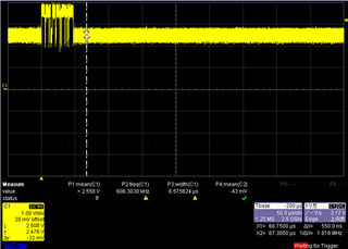
Normal 1MHz, Data 4MHz[Manual]

If there is a problem with the setting value or the approach to adjusting the register value is incorrect, please let us know.

Best regards,
O.H

  • Hi experts,

    I received additional information from a customer, so I would like to share it.

    Just to be sure, I would appreciate an answer to Q1 and Q2.

    Q3: Are there any problems with the register values ​​below?
    Pre = 0x0U, TSeg1 = 0x18U, TSeg2 = 0x4U, SJW = 0x4U
    They are using the calculation formula in the following thread, not the  "MCAN_BitTimingCalculator.xls".
    :e2e.ti.com/.../faq-tda4vm-can-how-is-bit-rate-calculated-for-can

    They sets CAN_CLK=100MHz and recalculated the value in C2000 with the tool.
    The result is the following value.

    Pre = 0x0U, TSeg1 = 0x11U, TSeg2 = 0x11U, SJW = 0x10U

    However, with the above settings, the data section was not sent, and communication was successful(250ns=4MHz) with the settings of Q3.
    It doesn't work well with the  "MCAN_BitTimingCalculator.xls", so if there are any other more appropriate calculation methods, please let me know.

    Normal 1MHz, Data 4MHz[Manual with E2E]

    By the way, regarding Q2, if CAN_CLK = 200 MHz, 200 ns (5 Mbps) was achieved.

    Best regards,
    O.H

  • Hi,

    Q1: the data baudrate = 40MHz / (seg1 + seg2 + 3) = 40/(7+0+3) = 4Mbps.

    Q2: Is 5MHz the maximum bit rate for the Data section for CAN-FD?

    Yes. MCAN CAN FD supports data baud-rate up to 5 Mbps and a payload size of up to 64 bytes per frame.

    Pre = 0x0U, TSeg1 = 0x11U, TSeg2 = 0x11U, SJW = 0x10U

    Please refer to DBTP register. The maximum TSEG2 is 0xF. Your setting (0x11) is out of the valid range.

  • Hi QJ Wang,

    Thank you for your reply.

    Sorry my mistake.
    The yellow highlights below are the corrected parts.
    Could you please comment again if there are any problems?

    Q3: Are there any problems with the register values ​​below?
    Pre = 0x0U, TSeg1 = 0x12, TSeg2 = 0x4, SJW = 0x4
    They are using the calculation formula in the following thread, not the  "MCAN_BitTimingCalculator.xls".
    :e2e.ti.com/.../faq-tda4vm-can-how-is-bit-rate-calculated-for-can

    They sets CAN_CLK=100MHz and recalculated the value in C2000 with the tool.
    The result is the following value.

    Pre = 0x0U, TSeg1 = 0xB, TSeg2 = 0xB, SJW = 0xA

    Best regards,
    O.H

  • Hi OH,

    I assume that Tseg1 and Tseg2 are the values programmed to CAN register

    For TSeg1=0x12, Tseg2=0x4, the sample point is (1+Tseg1+1)/(Tseg1+Tseg2 + 3) = 20/25 = 80%

    But 

    For Seg1 = 0xB, TSeg2 = 0xB, the sample point is (1+11+1)/25 = 56%

    Ideally, the bit time segments should be configured so that the sample point is as late as possible in the bit.

  • Hi QJ Wang,

    Sorry for the late reply.

    I understood. We will contact you again if the customer has any additional questions.

    Best regards,
    O.H

  • Hi O.H.,

    Did your customer run a test with TMDSCNCD28388D card which doesn't have a CAN transceiver?

  • Hi QJ Wang,

    [Details]
    The CAN communication pin of the TMDSCNCD28388D is connected to a CAN transceiver, and the CanBus is not connected to any other devices, only a termination resistor.
    The CanBus CANH signal is observed with an oscilloscope.

    The above is the environment.

    Best regards,
    O.H

  • O.H,

    If the transmitter loop delay is > the dataTimeSeg1, the TDC should be enabled, and TDCO/TDCF need to be programmed. The recommended sample point is >75%, or 80%.