This thread has been locked.

If you have a related question, please click the "Ask a related question" button in the top right corner. The newly created question will be automatically linked to this question.

TMS320F28379D: When the configuration is CPU1_RAM, it works fine, but when changed to CPU1_FLASH, it stops at ESTOP0

Part Number: TMS320F28379D
Other Parts Discussed in Thread: LAUNCHXL-F28379D, C2000WARE

Tool/software:

Hello,

I'm looking for a solution to my problem.

I am developing embedded software using CCS12.6 with LAUNCHXL-F28379D hardware.

The sample code I used is "gpio_ex2_toggle" and the CPU selection is CPU1 only.
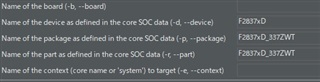
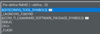
To match the hardware configuration of the LAUNCHXL-F28379D, change the package and part options in the Sysconfig->Basic option of the project properties to "F2837xD_337ZWT" and the Predefined symbol in C2000_Compiler Predefined symbol "_LAUNCHXL-F28379D" is added in C2000_Compiler.

In the early stages of software development, we were able to activate the CPU1_FLASH configuration and verify that we could write code to the internal FLASH ROM, that we could execute the expected operation, and that the software would work again even after the hardware reset button was pressed.
We have since switched the configuration to CPU1_RAM and added software functions. When the configuration is CPU1_RAM, the software runs as per the functions incorporated. However, when the configuration is switched to CPU1_FLASH, the software does not work.

In the software under development, the LED is turned on during the initialization of the peripheral in the main() routine.
After executing the build with the CPU1_FLASH configuration and writing to FLASH_ROM, when the hardware reset button is pressed, the LED lights up, so I assume that the software is able to execute until the middle of the main() routine.

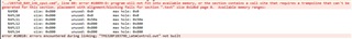
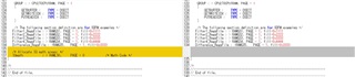
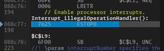
After that, the software stops at the breakpoint shown in the figure below, and disassembling the software shows that it stops at ESTOP0.

Are there any possible causes or countermeasures?

  • Hello,

    Just to verify:

    You haven't edited either of the linker cmd files (2837xD_RAM_lnk_cpu1.cmd and 2837xD_FLASH_lnk_cpu1.cmd), correct? 

    You are switching between build configurations using Build Configurations >> Set Active, correct?

    Can you look at the .map file after doing the flash build to verify that all the program symbols are correctly located in an area of flash memory?

    Best Regards,

    Delaney

  • Ms. Delaney,
    Thank you for your prompt reply.

    We needed to place a large memory size when adding functionality to the software. In doing so, the message shown below was displayed, so we took action based on another article in this forum.

    https://e2e.ti.com/support/microcontrollers/c2000-microcontrollers-group/c2000/f/c2000-microcontrollers-forum/1087166/tms320f28379d-error-10099-d-program-will-not-fit-into-available-memory-placement-with-alignment-fails-for-section-text-size-0x2b12

    Therefore, the linker file has been edited for both RAM and FLASH. The contents of the linker files for RAM and FLASH are attached.

    <2837xD_FLASH_lnk_cpu1.cmd>

    Fullscreen
    1
    2
    3
    4
    5
    6
    7
    8
    9
    10
    11
    12
    13
    14
    15
    16
    17
    18
    19
    20
    21
    MEMORY
    {
    PAGE 0 : /* Program Memory */
    /* Memory (RAM/FLASH) blocks can be moved to PAGE1 for data allocation */
    /* BEGIN is used for the "boot to Flash" bootloader mode */
    BEGIN : origin = 0x080000, length = 0x000002
    RAMM0 : origin = 0x000123, length = 0x0002DD
    RAMD0 : origin = 0x00B000, length = 0x000800
    RAMLS0 : origin = 0x008000, length = 0x000800
    RAMLS1 : origin = 0x008800, length = 0x000800
    RAMLS2 : origin = 0x009000, length = 0x000800
    RAMLS3 : origin = 0x009800, length = 0x000800
    RAMLS4 : origin = 0x00A000, length = 0x000800
    RAMGS14 : origin = 0x01A000, length = 0x001000 /* Only Available on F28379D, F28377D, F28375D devices. Remove line on other devices. */
    RAMGS15 : origin = 0x01B000, length = 0x000FF8 /* Only Available on F28379D, F28377D, F28375D devices. Remove line on other devices. */
    // RAMGS15_RSVD : origin = 0x01BFF8, length = 0x000008 /* Reserve and do not use for code as per the errata advisory "Memory: Prefetching Beyond Valid Memory" */
    RESET : origin = 0x3FFFC0, length = 0x000002
    XXXXXXXXXXXXXXXXXXXXXXXXXXXXXXXXXXXXXXXXXXXXXXXXXX

    <2837xD_RAM_lnk_cpu1.cmd>

    Fullscreen
    1
    2
    3
    4
    5
    6
    7
    8
    9
    10
    11
    12
    13
    14
    15
    16
    17
    18
    19
    20
    21
    MEMORY
    {
    PAGE 0 :
    /* BEGIN is used for the "boot to SARAM" bootloader mode */
    BEGIN : origin = 0x000000, length = 0x000002
    RAMM0 : origin = 0x000123, length = 0x0002DD
    RAMD0 : origin = 0x00B000, length = 0x000800
    RAMLS0 : origin = 0x008000, length = 0x000800
    RAMLS1 : origin = 0x008800, length = 0x000800
    RAMLS2 : origin = 0x009000, length = 0x000800
    RAMLS3 : origin = 0x009800, length = 0x000800
    RAMLS4 : origin = 0x00A000, length = 0x000800
    RESET : origin = 0x3FFFC0, length = 0x000002
    /* Flash sectors */
    FLASHA : origin = 0x080002, length = 0x001FFE /* on-chip Flash */
    FLASHB : origin = 0x082000, length = 0x002000 /* on-chip Flash */
    FLASHC : origin = 0x084000, length = 0x002000 /* on-chip Flash */
    FLASHD : origin = 0x086000, length = 0x002000 /* on-chip Flash */
    FLASHE : origin = 0x088000, length = 0x008000 /* on-chip Flash */
    XXXXXXXXXXXXXXXXXXXXXXXXXXXXXXXXXXXXXXXXXXXXXXXXXX

    We will check if all the other program symbols you mentioned are placed in the Flash memory area and will get back to you.

  • Hi Teruhiko,

    I see, sounds good. Just to verify, is all that you changed in the linker cmd files the .text allocation? 

    Best Regards,

    Delaney

  • Ms. Delaney,

    Thank you for your quick response.

    I am contacting you regarding changes to the Linker file.

    First, here are the changes to the FlashROM version of the Linker File.
    The left column is the modified version and the right column is the original.
    Initialized global variable area ".cinit" is now independent from the executable code area because an error occurred when sharing it with the executable code area.
    The global variable area ".bss" has also been extended.

    The IQmath Library is now also used, so I was added it to the "SECTION" based on the sample code.

    The next change is to the RAM version of the Linker File.
    As mentioned above, to accommodate the larger size memory allocation, the area size of RAMGS6 was set to 4000h and RAMGS7 - RAMGS9 were commented out.

    Because of the larger code size, the allocation of the ".text" area was changed. Allocation of ".bss", ".const", and ".data" areas was also changed.

    I have noticed so far, should IQMath.lib be placed in the FlashROM area? 

    I don't have much experience with embedded software. Is there a manual on how to set up the linker file?

  • Ms.Delaney,.

    I have checked the program symbols in the FlashROM version of the map file. As a result, all program symbols are located in the FlashROM area. 

    I think that the initialized global variables are placed in the “.data” area, so I don't see a problem with them being placed in the RAM area.


    ----------
    I was searching the forum for IQmath.lib placement in linker file. I came across the following article as a result. 

    https://e2e.ti.com/support/microcontrollers/c2000-microcontrollers-group/c2000/f/c2000-microcontrollers-forum/878674/faq-flash---how-to-modify-an-application-from-ram-configuration-to-flash-configuration

    In this article, the linker file for FlashROM is “(Ex: XXX_FLASH_lnk_cpu1.cmd at C2000Ware_x_xx_xx_xx_xx_device_support\XXX\common\cmd)”I found that it is stored in. Browsing this folder, I found a Linker file (2837xD_FLASH_IQMATH_lnk_cpu1.cmd) that seems to be related to IQmath.Lib. This file explicitly placed IQMath in the FLASH area, so I modified my linker file in the same way, and now my software can boot from FlashROM.

    Fullscreen
    1
    2
    3
    /* Allocate IQ math areas: */
    IQmath : > FLASHB, PAGE = 0, ALIGN(8) /* Math Code */
    IQmathTables : > FLASHC, PAGE = 0, ALIGN(8)
    XXXXXXXXXXXXXXXXXXXXXXXXXXXXXXXXXXXXXXXXXXXXXXXXXX


    Is it correct in assuming that the above is what was wrong in my linker file?

  • Hi Teruhiko,

    I will look into this and get back to you.

    Best Regards,

    Delaney

  • Hi Teruhiko,

    Yes, I believe that was your issue. Generally, if doing a flash build you always want to use one of the flash linker cmd files, and if using a library too, you should use the flash version of that library's linker cmd file (as you have mentioned). Here are some additional resources that may be helpful as well:

    Linked here is a guide about linker cmd files that should be helpful to look at.

    Please see the 3.6. Accessing IQmath Functions in the Boot ROM section of the IQMath user guide (linked here) for more information about using the IQMath library.

    Best Regards,

    Delaney

  • Ms. Delaney,

    Thank you for your respons. Thanks to your help, my software problem can be resolved. Too much thanks!!