This thread has been locked.
If you have a related question, please click the "Ask a related question" button in the top right corner. The newly created question will be automatically linked to this question.
Tool/software:
Hi everyone,
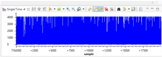
I am working on a radiation detection project. I need to sample the output of amplifier circuit (Cremat) with ADC in C2000 Launchpad. I am sure that the code and connections are ok. When I measure the output of the amplfier by oscilloscope, I can see the gamma peak which is shown in picture below. However, when I conenct the output of the amplifier to the ADC input of C2000, I see strange data on the graph. could you please help me if I miss somethnig like impedance matching etc.?
Hi,
Please see our app note on ADC input circuit design: https://www.ti.com/lit/spract6
I don't think the content covered in that app note will be the cause your error, since that would normally cause your output to be lower than expected.
Are you sure that you set the graph up correctly? If you store ADC results in a buffer, are you seeing most of the samples be close to 4096?
Are you using on of our examples? If so, which one?
Best Regards,
Ben Collier
Hi,
Yes I am using buffer and most of the samples 4095 as you said. The graph should be ok. The code is attached below. I use TI example for buffer and the left is my work.
//########################################################################### // Author: Halit Durukan //########################################################################### #include "F28x_Project.h" // Device Headerfile and Examples Include File #define ADC_BUF_LEN 1000 //########################################################################### // Global variables used in the project before main function. Declare other // variables in this section of the code. //########################################################################### Uint16 Result = 0; Uint16 AdcBuf[ADC_BUF_LEN]; //########################################################################### // Declare the service routines and functions //########################################################################### interrupt void xint1_isr(void); interrupt void cpu_timer(void); interrupt void adcint1_isr(void); //###################### Beginning of the main code ####################### void main(void) { // Initialize System Control: // PLL, WatchDog, enable Peripheral Clocks // This example function is found in the F2837xD_SysCtrl.c file. InitSysCtrl(); // Clear all interrupts and initialize PIE vector table: // Disable CPU interrupts DINT; // Initialize the PIE control registers to their default state. // The default state is all PIE interrupts disabled and flags // are cleared. // This function is found in the F2837xD_PieCtrl.c file. InitPieCtrl(); // Disable CPU interrupts and clear all CPU interrupt flags: IER = 0x0000; IFR = 0x0000; // Initialize the PIE vector table with pointers to the shell Interrupt // Service Routines (ISR). // This will populate the entire table, even if the interrupt // is not used in this example. This is useful for debug purposes. // The shell ISR routines are found in F2837xD_DefaultIsr.c. // This function is found in F2837xD_PieVect.c. InitPieVectTable(); // Enable global Interrupts and higher priority real-time debug events: //EINT; // Enable Global interrupt INTM //ERTM; // Enable Global realtime interrupt DBGM //########################################################################### // User specific code: Your code comes here. //########################################################################### EALLOW; AdcaRegs.ADCCTL2.bit.PRESCALE = 6; //set ADCCLK divider to /4 AdcaRegs.ADCCTL1.bit.ADCPWDNZ = 1; //power up the ADC AdcaRegs.ADCCTL1.bit.INTPULSEPOS = 1; //Set interrupt pulse positions to late AdcaRegs.ADCCTL2.bit.RESOLUTION = 0; // 12-bit resolution AdcaRegs.ADCCTL2.bit.SIGNALMODE = 0; // Single-ended (12-bit mode only) DELAY_US(1000); //have to delay at least 500 microseconds before using ADC AdcaRegs.ADCSOC0CTL.bit.CHSEL = 0; //SOC0 will convert pin ADCINA0 AdcaRegs.ADCSOC0CTL.bit.ACQPS = 39; //0.2 micro seconds for sampling window (40 x 5ns = 0.2 micro secs) AdcaRegs.ADCSOC0CTL.bit.TRIGSEL = 0x01; //trigger on CPU Timer 0 CpuTimer0Regs.PRD.all = 10000 - 1;//Load period value. 20 kHz sampling (50 micro seconds period) CpuTimer0Regs.TPR.bit.TDDR = 0;//Set the prescale value for the timer as 1. CpuTimer0Regs.TCR.bit.TSS = 1;//Stop the timer. CpuTimer0Regs.TCR.bit.TRB = 1;//Reload the timer. CpuTimer0Regs.TCR.bit.TIE = 1;//Enable the Timer0 interrupt in the peripheral level. CpuTimer0Regs.TCR.bit.TSS = 0;//Start the timer. AdcaRegs.ADCINTSEL1N2.bit.INT1SEL = 0; //EOC0 will set INT1 flag AdcaRegs.ADCINTSEL1N2.bit.INT1CONT = 1; //interrupts will be generated //whether the ADCINTFLG is //cleared or not AdcaRegs.ADCINTSEL1N2.bit.INT1E = 1; //enable INT1 flag //Redirect the address of the ISR: PieVectTable.ADCA1_INT = &adcint1_isr; PieCtrlRegs.PIECTRL.bit.ENPIE = 1; // Enable the PIE block PieCtrlRegs.PIEIER1.bit.INTx1 = 1; // Enable PIE Group 1 INT1 ADCA1 IER |= M_INT1;//Enable CPU INT1 includes Xint1 EINT;//Enable global interrupt mask INTM. ERTM; EDIS; for (;;) { } } //###################### End of main code ####################### //#################### Interrupt Service Routines ################# interrupt void adcint1_isr(void) { static Uint16 *AdcBufPtr = AdcBuf; *AdcBufPtr++ = AdcaResultRegs.ADCRESULT0; // Brute Force the circular buffer if (AdcBufPtr == (AdcBuf + ADC_BUF_LEN)) { AdcBufPtr = AdcBuf; } //Result = AdcaResultRegs.ADCRESULT0; GpioDataRegs.GPBTOGGLE.bit.GPIO32 = 1; PieCtrlRegs.PIEACK.all = PIEACK_GROUP1; }
Dear Benjamin,
I solved my problem but would like to inform you about the problem I faced because the solution and the problem itself are very funny :D The last time I got correct result was yesterday. Since then, I have searched every single documentations from datasheets to forums. I was changing my sampling window (ACQPS) and sampling freq, however it din't work at all. After numerous same trivial, I started to feel like an idiot because it suddenly worked! Can you guess what changed? Just PC was unplugged :D For some reason I needed to fix my computer in the past, now it is clear that a few cable or screws are out :D when I plug PC and employ the C2000, it reads periodic noise for some reason.