This thread has been locked.

If you have a related question, please click the "Ask a related question" button in the top right corner. The newly created question will be automatically linked to this question.

TMS320F28069M: SCI bootloading

Part Number: TMS320F28069M
Other Parts Discussed in Thread: C2000WARE, LAUNCHXL-F28069M

Tool/software:

Hi community,

So, recently I was developing a software on LaunchXL f28069m.

Now As I have completed the development, I want to load the code in the custom PCB I made for my application.

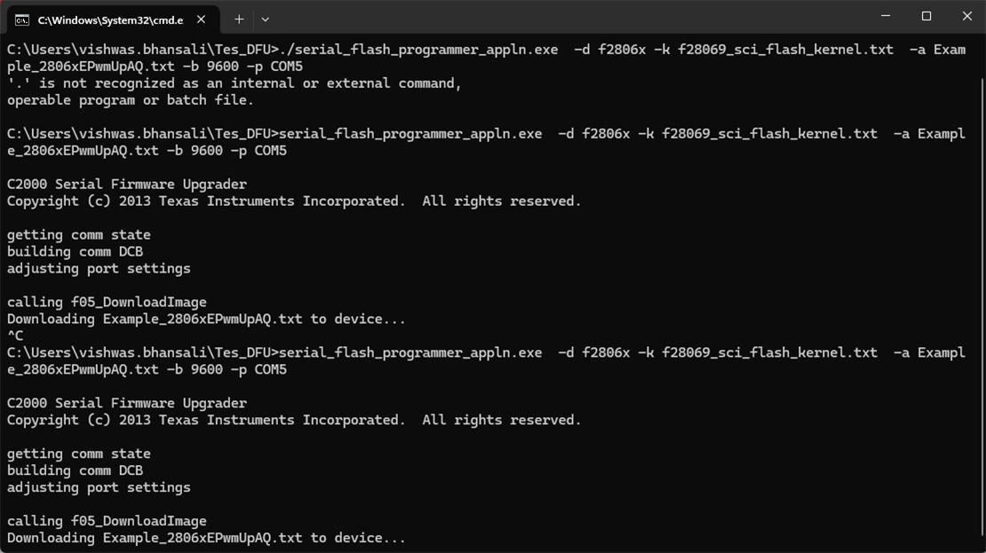
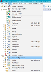
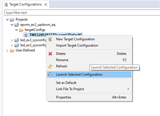
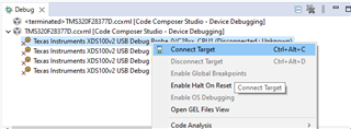
I came to know that I can use SCI bootloader for Flashing the code but still I'm clueless as how to do that.

It would be great if someone help me.

Thanks, 

Vishwas 

  • Hello Vishwas,

    The first place to start is getting familiar with the device TRM Boot ROM chapter 2 - specifically the subchapters on bootloading and boot modes. There is an SCI boot mode (see 2.2.16). I would recommend our serial flash programmer guide as well, - though it targets other C2000 devices, a similar process would be used to accomplish loading code via SCI to a device. 

    The SCI bootloader source code is available in C2000Ware (C:\ti\c2000\C2000Ware_5_02_00_00\libraries\boot_rom\f2806x\v1_1\rom_sources\source). 

    Let me know if you find these helpful and are able to utilize them.

    Best Regards,

    Allison

  • Hi Allison,

    I did Try to boot with the reference from Serial Flash Programming of C2000Tm Microcontrollers and got this

    I don't know maybe stuck there or maybe stuck in while where it waits for host to send message.

    Can you guide me on what's happening.

    Thanks,

    Vishwas

  • Hello,

    I cannot access file sharing sites like google drive for security reasons. 

    Can you please provide more context here? What stage of development are you in - are you trying to utilize the serial flash programmer? What steps are you performing and at what step in the sequence are you getting stuck? What indicates that you are having an error (what is the symptom of the issue)? It is difficult to assess unless I understand more where you are at and what you are doing.

    Best Regards,

    Allison

  • Hi,

    This is the Image which I was sharing using that link.

    What stage of development are you in - are you trying to utilize the serial flash programmer?

    Yes, Actually I did develop my application using LaunchXL-F28069M but now I want to upload that code to the application PCB, for that purpose I'm using Serial Flash Programmer.

    What steps are you performing

    Actually, I'm referring to a YouTube Video: (1518) SCI Bootloader using TMS320F2837xD - YouTube

    In case, if you are not able to access this the steps which This video provide are: 
    1. Modify Serial Flash Kernel Code Composer Studio Project File
    To be imported from C2000Ware library directory C:\ti\c2000\C2000Ware_5_02_00_00\device_support\f2806x\examples\c28\f28069_sci_flash_kernel

    3. Re-compile the project and CCS Compiler “Hex Utility” being enabled to generate TI ASCII txt formatted file.

    4. create one working directory for yourself in Windows C: drive. It can be: C:\Temp if you have write access to C: drive. Otherwise, you can create inside: C:\Users\vishwas.bhansali\Tes_DFU (just an example, you need to adapt accordingly), then you would need to copy all the required files (only 3 files) to that working directory and run the command from that directory by changing directory to: cmd C:\Users\hadiyat\Test_DFU
    a) Programmer Executable File: “serial_flash_programmer_appln.exe”
    Copy from C:\ti\c2000\C2000Ware_5_02_00_00\utilities\flash_programmers\serial_flash_programmer\serial_flash_programmer_appln.exe
    b) MCU Kernel TI txt file: “f28069_sci_flash_kernel.txt”
    Copy from C:\ti\c2000\C2000Ware_5_02_00_00\utilities\flash_programmers\serial_flash_programmer\F286x\f28069_sci_flash_kernel.txt
    c) Application File: “Example_2806xEPwmUpAQ.txt” (by using "Hex Utility" I can generate txt file)
    Copy from C:\ti\c2000\C2000Ware_5_02_00_00\utilities\flash_programmers\serial_flash_programmer\F286x\Example_2806xEPwmUpAQ.txt

    5. then open cmd on
    C:\Users\vishwas.bhansali\Tes_DFU
    And then, copy the:
    serial_flash_programmer_appln -d f2806x -k f28069_sci_flash_kernel.txt -a Example_2806xEPwmUpAQ.txt -b 9600 -p COM5

    at what step in the sequence are you getting stuck?

    What I think that the Host Device first download kernel to the target device then from there Kernel take control and upload the application in Flash memory.
    So, as it is saying in the image that it is downloading the application in device maybe it is and second stage.
    Correct me if I'm wrong.

    What indicates that you are having an error (what is the symptom of the issue)?

    As, it is got stuck at that particular statement of downloading Example_2806xEPwmUpAQ.txt to device and not moving further is where I think I start believing I have an error.

    Thanks for you quick response,

    Vishwas

  • Hi Vishwas,

    Thanks for sending the information. As described in the TRM (2.2.16 SCI_Boot Function), the device should perform a handshake with the serial flash programmer using autobaud functionality where the programmer host sends an initial word and the device uses this to calibrate the SCI baud rate and echoes the data back to confirm.

    When I recently ran this for another C2000 device, the programmer message was as seen below:

    It doesn't look like we are getting to that autobaud step in the sequence, so the question is where are we getting stopped? The first thing I'd check is are you booting up the device in SCI boot mode? So are you booting the device without debugger connected and with the boot pins set for SCI boot mode? If yes, we can see where else might cause a disconnect. 

    Best Regards,

    Allison

  • Hi Allison,

    Thanks for your response.

    So are you booting the device without debugger connected and with the boot pins set for SCI boot mode?

    Yes, I'm not using any debugger, I'm using an UART module for communication between PC and device.
    And yes, I've been set boot pins to SCI boot mode by selecting TRST/J_TRST = 0, TDO = 0, GPIO34 = 1. 

    Yes, that's all I'm doing for now.

    Best Regards,

    Vishwas

  • Hi Vishwas,

    Can you connect to the device using CCS when the flash programmer exe stops to see where the device is in the bootloader to double check?

    Another thing to check is verifying the COM number is correct - I assume you've already done this, though.

    Best Regards,

    Allison

  • Hi Allison,

    Can you connect to the device using CCS when the flash programmer exe stops to see where the device is in the bootloader to double check?

    Can you Guide me how to do that?

    Another thing to check is verifying the COM number is correct

    Yes, the COM number is correct, and I had verified it.

  • Hi Vishwas,

    Loading symbols can be a valuable debug method. This option adds the symbols available in the generated project '.out' file for debugging purposes instead of loading the actual '.out' program onto the core via CCS. Boot the device, connect to the host programmer, and proceed with the command to execute the serial flash programmer. Once the it pauses:

    1. Open CCS to a workspace
    2. Click 'view' > 'target configurations':
    3. You can import a project for this device to CCS and use that to connect to the device, or copy the raw target config from C2000Ware to the "user defined" target configurations in this window. Either way, find the device target config (example for F28377D below) and launch it:
    4. When it brings up the debug window, select the device CPU and connect to the target:
    5. Navigate to the toolbar and click the button to "load symbols"
    6. Load the bootrom .out file. For this device, it should be in 
      1. C:\ti\c2000\C2000Ware_5_02_00_00\libraries\boot_rom\f2806x\v1_1\rom_sources\Release
      2. If a window pops up saying it can't find the source file, you can select "Locate File" and find it in C2000Ware
        1. Usually here C:\ti\c2000\C2000Ware_5_02_00_00\libraries\boot_rom\f2806x\v1_1\rom_sources\source
    7. The file should open to show the location of the bootrom you are at, and you can step through/debug

    Let me know if you are able to get it working - there are also other threads that likely have instructions on how to do this as well.

    Best Regards,

    Allison

  • Hi Allison, 

    I did try to do the mentioned steps but in step: 4 Connect the target I'm getting this error

    Maybe this is because of the connection I have which is like:

    An USB connection from PC to UART Driver module then UART Driver module to Device.

    There is no XDS100v2.

    If I'm right, then is it so without using XDS USB Debug Probe we cannot debug a custom board. 

    But if we can debug without using XDS USB Debug Probe, how can we do that?

    Best Regards,

    Vishwas

  • Hi Allison,

    This is how I'm trying to connect to my custom board.


    Please review it and provide your valuable input regarding this and tell me I'm doing anything wrong.

    Thanks,

    Vishwas

  • Hi Vishwas, 

    Please allow for another day for me to form a response. Thanks for the patience.

    Best Regards,

    Allison

  • Hi Vishwas,

    My sincere apologies, I misread your earlier post and thought you were using a board with debuggerFrowning2. You are correct that without the Debug probe you cannot carry out the steps I mentioned.

    Unfortunately, it is very difficult to tell what is going on without being able to connect to the device and debug. Assuming your boot pins are indeed correct, the last suggestion would be to probe/monitor the power rails and XRSn to see if the device is booting properly, otherwise the suggestion is to get a evaluation board or debugger to help give visibility into the device/program.

    Let me know if you'd like any debug probe recommendations. There are some fairly inexpensive options available online.

    Best Regards,

    Allison

  • Hi Allison,

    Could you please define what results should I have while testing/checking the power rails or XRSn pin!!!!

    otherwise the suggestion is to get a evaluation board or debugger to help give visibility into the device/program.

    I do have an evaluation board LaunchXL-F28069m.
    So please tell me what can I do to get the visibility.

    Let me know if you'd like any debug probe recommendations. There are some fairly inexpensive options available online.

    Yet I had ordered an XDS-100v2 usb debug probe, it will be great to look at other options.

    Thanks,

    Vishwas

  • Hi Vishwas,

    The devices contain a device reset (XRSn) pin that resets the device when driven low. This pin is also driven low upon power-on reset (POR), brownout reset (BOR), or watchdog reset. You can monitor the power rails to watch them latch when XRSn releases. If XRSn is toggling, this means the device is getting reset by the watchdog every number of cycles. If you are not resetting regularly, then you are waiting in a dedicated boot mode that has disabled the watchdog. 

    I have the same eval board and went to try this out myself. I'm currently running into a similar issue you see where autobaud isn't occurring. I believe it may just be the format of the file being sent, but let me check with those who maintain this flash kernel example and update on my progress.

    Just wanted to add that there is a guide here for the launchpad https://www.ti.com/lit/ug/sprui11b/sprui11b.pdf

    Best Regards,

    Allison

  • Hi Allison,

    If XRSn is toggling, this means the device is getting reset by the watchdog every number of cycles

    This is exactly what happening with XRSn pin, it is continuously toggling with the frequency of 63Hz.
    I think which mean that I have not properly boot the device.
    But as of now I have set the switches as: 
    GPIO34: 1
    TDO: 0
    TRST: 0
    Even though it is happening like this why!!!!!!!

    I'm providing the schematic of my board please look at it and tell me if something is wrong

    Thanks,

    Vishwas

  • Hi Vishwas,

    Thank you for the information. Let me consult with a colleague when we are back in office tomorrow and provide another recommendation. I think it may be good to consider testing with use emulation boot in this case as well.

    Best Regards,

    Allison

  • Hi Allison, 

    To cross check whether there is problem in hardware it might be possible that the boot mode pin did not change accordingly. I did check particular pins From the IC itself and got the same the result as it should have to SCI boot mode.

    So, This I can say that 
    GPIO34 = 1
    TDO = 0
    TRST = 0

    While searching why this type of problem is occurring, I got these two blogs.
    TMS320F280049: In stand alone mode, the watchdog will continuously reset the device. - C2000 microcontrollers forum - C2000Tm︎ microcontrollers - TI E2E support forums
    CCS/TMS320F280049: device stand alone run fail - C2000 microcontrollers forum - C2000Tm︎ microcontrollers - TI E2E support forums
    Which Discuss how the watchdog problem I'm facing they also faced and how they overcome from that issue.

    From these posts I get to know that the problem lies in CodeStart_Branch.asm file there we need to disable Watchdog and then move forward.

    But the codestart file I have is already have the watchdog disable, maybe it could something else also.

    Please look at it.

    thanks 

    Vishwas

  • Hi Vishwas,

    Thank you for more input. Let me review these threads and information and provide further assessment. As always, I appreciate your patience in this.

    Best Regards,

    Allison

  • Hi Vishwas,

    I'll be able to provide an update for you by early next week.

    Thanks,

    Charles

  • Vishwas,

    Apologies for the delay, but do you still need assistance with this issue?

    Thanks,

    Charles

  • Charles, 

    Yes, Charles I'm yet stuck at the same situation could you please help me out.

    Thanks,

    Vishwas

  • can all this work without external oscillator?

    or there is need of oscillator for sci bootloading or even loading the code through xds100v2.

  • Hi Vishwas,

    Charles is unfortunately unable to support this further. I just returned from out of office but will take a second look this week. Thanks again for the patience. Also, this should be fine without need for external oscillator.

    Best Regards,

    Allison

  • Hi Allison, 

    I hope you are doing well

    did you find something?

    Best Regards,

    Vishwas

  • Hi Vishwas,

    I may have figured out the issue, but I am running into a bug with our serial flash programmer. I'm checking with the team right now to verify/correct it and will provide an update as soon as I can run my check. 

    In the meantime, could you:

    1. Set the switches for emulation boot, power on the device, launch the target configuration to connect to it, and open the memory browser check the memory at 0x0D00/0x0D01 etc. and send me a screenshot of the values there.

    2. Set the switches for SCI boot and send a picture of your switch settings on the launchpad so I can double check?

    Best Regards,

    Allison

  • Hi Allison,

    1. Set the switches for emulation boot, power on the device, launch the target configuration to connect to it, and open the memory browser check the memory at 0x0D00/0x0D01 etc. and send me a screenshot of the values there.

    Does it will happen without a debugger!!!!!

    Best Regards,

    Vishwas

  • Hi Vishwas,

    Allison is out of office today, returning tomorrow, please expect a response back by then.

    Thank you,

    Luke

  • Hi Vishwas,

    Just wanted to provide an update that I'm still facing issues verifying this. I'm looping in a few others internally as well and will provide an update for you later this week. A colleague and I are currently using the F28069 launchpad to test this, which is why I listed the emulation boot suggestion (for the launchpad) so we can verify the process for the device as the same would apply to the custom PCB. Again, the process should follow what is listed directly in the Serial Flash Programming app linked earlier. 

    To clarify, you are still able to load the flash kernel into the RAM of the device, but are unable to load the application code into the device FLASH? Can you please describe how you are generating the application code .txt file? I know you are using the hex utility as you stated earlier - but what steps did you take to do so? Is the project set to the FLASH build configuration (there are different linker command files needed for a project being loaded to RAM vs. FLASH). 

    Best Regards,

    Allison

  • Hi Allison,

    which is why I listed the emulation boot suggestion

    I think it is not possible to use emulation boot mode without debug probe. Right!!??
    so as I don't have debug probe that's why I can't use it.

    you are still able to load the flash kernel into the RAM of the device

    According to this kernel image has been downloaded but it got stuck while downloading the application code.

    Can you please describe how you are generating the application code .txt file?

    Is the project set to the FLASH build configuration (there are different linker command files needed for a project being loaded to RAM vs. FLASH). 

    As of now I have not made any changes in build configuration, I'm using ram linker command file only.

    Regards,

    Vishwas 

  • Hello Vishwas,

    I was able to run this successfully using the following steps on the Launchpad F28069M evaluation board:

    1. Import the F2806x SCI flash kernel example to CCS (<Local C2000ware root>\device_support\f2806x\examples\c28\f28069_sci_flash_kernel)
      1. Right click on the project in the project explorer, select properties -> Build -> Steps. Verify that the project is configured as follows
      2. Build the flash kernel project 
      3. Copy the f28069_sci_flash_kernel.txt output file in the project's Debug folder and paste to the same directory where the serial_flash_programmer.exe is located
    2. Configure the application's project properties to output the .txt application output
      1. Similar to step 1a, ensure that "${CG_TOOL_HEX}" "${BuildArtifactFileName}" -boot -sci8 -a -o "${BuildArtifactFileBaseName}.txt" is in the post build steps for the application project
      2. Exclude the RAM linker cmd file by right clicking on it and selecting Exclude from Build from the dropdown menu
      3. Copy in the Flash linker cmd file located at <Local C2000ware root>\device_support\f2806x\common\cmd\F28069M.cmd into the project 
      4. Build the project
      5. Copy the application .txt output file in the project's Debug folder and paste to the same directory where the serial_flash_programmer.exe is located
    3. Configure the device for SCI emulation bootmode
      1. Make sure TRST == 1 so you can use emulation boot mode
        1. For the launchpad, this can be done manually with S1 as seen below                                                         
      2. Start a Debug session and go to View -> Memory Browser
      3. Locate address 0xD00 to configure the SCI emulation boot configuration as below                                 
        1. If not using a debugger, configure the SCI standalone boot
      4. Reset the CPU so the device emulates SCI boot mode and jumps to the SCI boot loader
    4. Run the flash programmer with the command line: ./serial_flash_programmer.exe -d f2806x -k YOUR_FLASH_KERNEL.txt -a YOUR_APPLICATION.txt -p COM# -b 9600 -v 
      1. Ensure that the red text is adjusted to accordingly
      2. The flash kernel and application should both load