TMS320F28377D: The DSP28377D is causing the crystal oscillator to fail to work.

Part Number: TMS320F28377D

Tool/software:

Hello, I have a question regarding my DSP28377D board. It has been running normally for some time, but occasionally (it has happened many times, with a probability of about 1%) the program fails to run. Based on experience, I first checked the crystal oscillator (a passive crystal oscillator), and found that it was not oscillating. During troubleshooting on multiple problematic boards, we encountered the following phenomena:

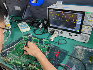
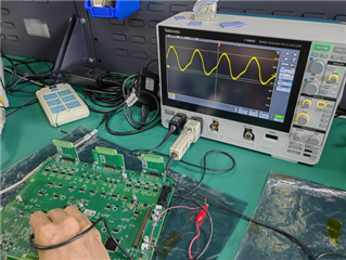
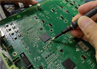
1. When attempting to use an oscilloscope to observe whether the crystal oscillator was working, just by touching the load capacitor with the oscilloscope probe, the board started functioning correctly, and the program ran as expected. This happened with some of the boards.

2. On problematic boards, using hot air or an oven to heat them also resulted in the boards functioning correctly, and the program ran as expected. This occurred with some of the boards.

3. For most boards, the above methods did not resolve the issue.

4. By replacing the crystal oscillator with a new one, we still found that the new crystal did not oscillate.

5. By replacing the DSP28377D chip, the board functioned normally.

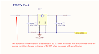
6. The resistance across the load capacitors on normally functioning boards is 1.2 MΩ, while the resistance across the load capacitors on malfunctioning boards is 2.3 kΩ.

Could you please advise me on how to troubleshoot this issue? This problem has occurred many times now. Thank you!

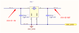
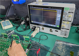
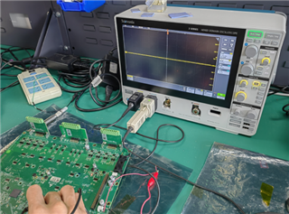
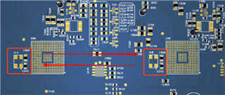
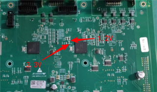
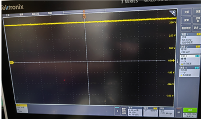
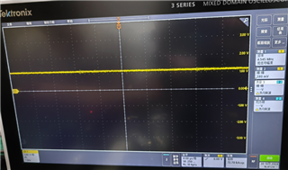
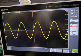
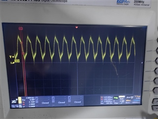
The circuit diagram connecting the crystal oscillator to the DSP is shown below, and the waveform of the malfunctioning crystal oscillator is also shown below:
  • Hi Hui,

    I have not had the chance to check the X1 resistance but that is an interesting observation.  I will do that on some parts here.  In addition, can you provide the following:

    1.) X1 and X2 waveforms (please use the same scale) for the bad part and for the good 28377D chip.  Please use a very low capacitance probe or active probes so as not to load the crystal pins.

    2.) Do you have the characteristics/specifications of the crystal?

    Thanks,

    Joseph 

  • Hi Hui,

    I measured high impedance (Mohm) on the X1 pin.  Seems that there is anomaly on the part that you have that has only 2.3Kohms on X1.  Would you be able to take a picture on the unit on the top side, showing all the characters and send it out?  Also, do you work with a TI Application/Sales field person on your F28377D project?

    Thanks,

    Joseph

  • Hi Joseph,

     Below is the schematic diagram showing the connection between the crystal oscillator and the DSP28377:

    Additionally, we have communicated with after-sales technical support, who suggested that we seek help on the forum!

    Thanks,

    Hui

  • Hi Joseph

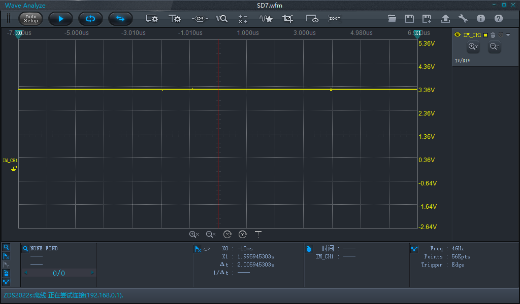
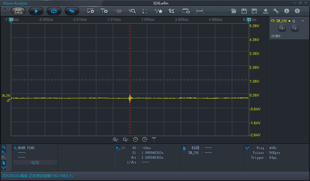
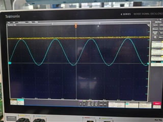
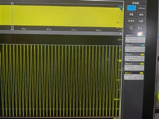
    1. On the problematic boards, we measured the waveforms at X1 and X2, as shown in the figure below:

    2. The specification sheet for the crystal oscillator we used:

    7B20000023.pdf

    We also observed an interesting phenomenon: the failure rate significantly increases under high temperature conditions (around 60°C).

    Thanks!

  • Hi Hui,

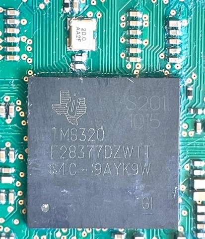
    Thanks for the confirmation.  Can you please take a photo of the F23877D chip showing the device markings?  Please contact field/sales to initiate returns analysis on the particular unit that showed this issue.

    Best regards,

    Joseph

  • Hi Joseph,

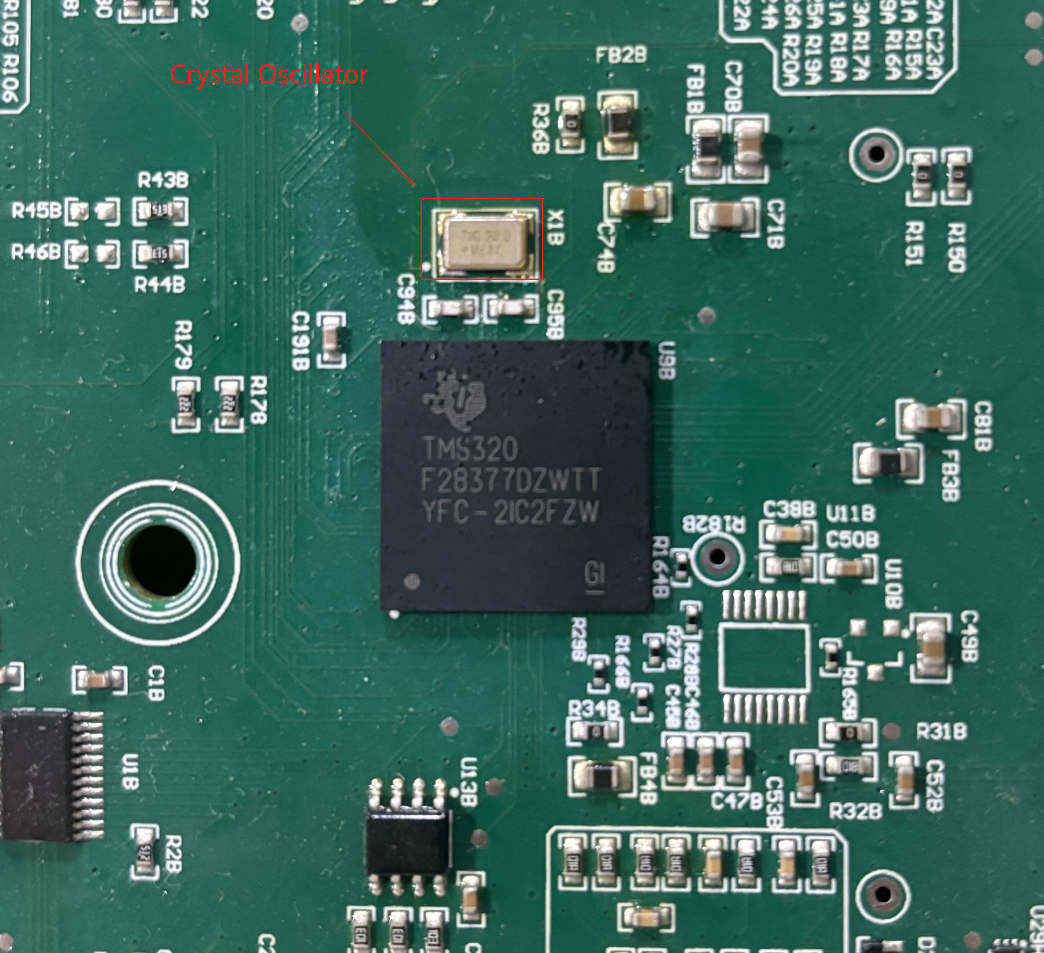
    Thank you for your reply. Here is a photo of our 28377D chip:

    The reason is as follows: since our company's annual usage is only 10K, the official technical analysis is not very friendly. Therefore, we can only seek support here to find solutions to this problem.

    Yesterday during testing, we observed an interesting phenomenon: on the faulty boards, when the oscilloscope probe made contact, the chip started working again. Then we tested it under high temperature (60°C) for a period of time, and the chip stopped working again, and the crystal oscillator did not oscillate.

    Thanks,

    Hui

  • Hi Hui,

    I've contacted our returns analysis team to see how we can proceed.  Please allow us up to the end of this week to get some response.

    Thanks and regards,

    Joseph

  • Hi Hui,

    Based on the device markings, looks like your parts were acquired from distributor.  Can you please confirm how your parts were sourced?  This may lead us to a path for returns analysis.

    Thanks,

    Joseph

  • Hi Hui,

    Since this is acquired from Arrow, please get in touch with Arrow to get the unit to TI's return network support.

    Regards,

    Joseph

  • Hi Joseph,

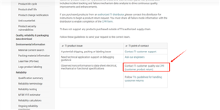
    After communicating with Arrow, he suggested that we follow the steps below to send the items to the specified location directly. Would this approach work for you?

    Hui

  • Hi Hui,

    Checking with our quality team if this is the correct way to do it.  Will keep you posted.

    Regards,

    Joseph

  • Hi Hui,

    I confirmed with our production and quality teams that it is the correct way to initiate the returns.  Please proceed.

    Thanks and regards,

    Joseph

  • Hi Joseph,

    There is an issue I need to bring to your attention: The DSP28377D chips we purchased have been in use for over a year, so we are still in the process of sending them to you for analysis. In the meantime, we conducted the following tests ourselves to try and identify the issue:

    1. Using an oscilloscope probe with minimal capacitance, touching the chip did not cause it to return to normal operation.

    2. Touching the chip with a multimeter probe for an extended period did cause the chip to return to normal operation.

    Do you have any suggestions?

    Thanks!

    Hui

  • Dear all,

    I am investigating exactly the same phenomenon on two products returned from our customer fields.

    The components are the TMS320F28377DZWTT. When the product is power supplied,  after an amount of time, the oscillator stops and the product is "locked" (oscillator is not able to start), I mean, even after multiple power supply switching of the product, the oscillator does not starts anymore.

    The only way to recover is to apply a short circuit between X1 and GND, then I switch off and on the product and the oscillator starts correctly.

    When the product is locked (oscillator not started), the resistance across the load capacitors is 7 kΩ to 50 kΩ.

    Here is one of the MCU having this behaviour:

    I am going to check if the temperature has an effect. 

    Best regards

    JDM

  • Hi Jean-Martin,

    Yes, please evaluate this at high temperature.  Please measure the resistance of X1 to GND on a working board as well.

    Thanks and regards,

    Joseph

  • Hi Joseph,

    Thank you for your reply. After reviewing your response, I feel that this situation is somewhat similar to ours, and we will carefully examine it.

    However, I need to update you on our latest test results:

    1. The latest feedback from the original manufacturer is that they can only perform FA (Failure Analysis) on date codes within one year. Our chips are past that date, so they cannot conduct FA.

    2. In our recent tests, we found that what previously could be restored by briefly touching the chip with an oscilloscope or multimeter probe no longer works, or is much harder to restore.

    3. In today's tests, we discovered that the resistance between X1 and GND is around 330 kΩ, whereas the resistance between X1 and GND on a normal chip is 16.6 MΩ (there is some discrepancy compared to previous measurements).

    Hui

  • Hi Jean-Martin,

    Thank you for sharing your case. Have you identified the cause of the issue? Do you have any suggestions?

    Thanks,

    Hui

  • Hi Joseph & Hui,

    When our product is locked (oscillator does not start), I switch off the product and I measure the resistance of X1 to GND an impedance which increase with the time, starting from 2 kΩ until 50 kΩ.

    When our product can start normally, this impedance is 3 MΩ.

    When the temperature of the component increases above 65°C, the oscillator stops and get locked until a short ciruit on X1 pin or after a very long period (2 days) of switch off of the product.

    thanks

    JDM

  • Hi Jean-Daniel,

    Did you also get the chance to swap another BGA part like what Hui did or remount (reflow) the 256BGA probably to see if it may be caused by solder issue? 

    Thanks and regards,

    Joseph

  • Hi Joseph & Hui,

    a very long period of switch off at ambiant temperature does not help to leave the locked state, that is to say, the I leave the two product in power off and 60 hours after, I switch on the power supply and the oscillators does not start. 

    We will not swap with another part because we have no reflow machine and we prefer to send the 2 problematic boards for a X-ray inspection.

    I have no more idea for the investigations. 

    Knowing how the oscillator get locked (temperature >60°C) and how to recover (short-circuit to GND on X1 pin), this is going to help us for trying to detect problematic boards.

    best regards,

    JDM.

  • Hi Jean-Daniel,

    XRAY will probably not show you anything.  You can probably start with fulfilling the returns flow process described above to start the analysis with our quality team.

    Best regards,

    Joseph

  • Hi Heseph,

    In our recent tests, we have made some new observations: After discovering that briefly touching the chip with an oscilloscope or multimeter probe did not restore normal operation, we left the chip for some time. As of today, the chip still does not return to normal operation. Additionally, the resistance between X1 and GND has changed from 330 kΩ to 3.3 kΩ. Is the chip completely damaged? Do you have any other suggestions for further testing?

    Thanks!

    Hui

  • Hi Hui,

    We'll let our returns team evaluate the issues you are seeing to confirm what went wrong.  Have you initiated the return process yet?

    Best regards,

    Joseph

  • Hi Joseph,

    1. We tried to get help through the official CPR process, but when filling in the "Enter location where return is coming from ", all the information provided by the supplier was entered and it prompted "Invalid location", so the process could not be submitted

    2. Supplier feedback does not go through the official process, they communicate with the original factory for FA (failure analysis), but the original factory feedback, they can only do FA (failure analysis) on the date code within one year. Our chips are past that date, so they can't do FA.

    So we wanted to see if we could get some help here

    Thanks!

    Hui

  • Hi Chen,

    Let me talk to our internal returns team and let you know their advise.

    Regards,

    Joseph

  • Hi Hui,

    Quoting the response from our field team in CN:

    =======

    Hi Joseph,


    You can ask customer to submit the CPR in below link following the attached instruction.


    For customer concern:

    1. Location should be “Chengdu” per customer name
    2. One year is TI deviec warranty not means TI will not accept the FA for the materials after 1 year.


    Thanks.

    ========

    Hope this helps you with your return process.

    Regards,

    Joseph

  • Hi Joseph,

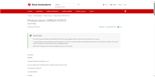
    Thank you very much for your help. We have initiated the CPR process according to the link you provided and hope to get the help of TI's FA.

    Thanks!

    Hui

  • Hi Hui,

    Ok, closing this post for now.  In case you run into issues, please open another post on this forum.

    Regards,

    Joseph

  • Thank you for your coordination. We have received the failure analysis report from TI. May I ask whether it can be determined from this report whether the EOS is induced by ESD introduced during the circuit board patching process or caused after the circuit board is powered on?QEM-CCR-2409-00926 Report.pdf

  • Hi Hui,

    Failure analysis report only provides the reason why the part failed, in this report it was determined to be electrical overstress (EOS).  Failure analysis however cannot pinpoint where in your process the damage has occurred.  You would need to isolate this in your process.

    Regards,

    Joseph

  • Hello,

    I would like to send my defective component to launch a Failure Analysis by TI, in order to understand the problem.

    I have been in contact with the firm which manufacture our products, but the traceability is not enough deep to get the detailed purchase information (customer reference/tracking #, Sales order number SO#, Purchase order number PO#, Delivery document number DN#).

    Is there another way for sending the component to TI and launching a FA ?

    Best regards,

    JDM

  • Hi Jean-Daniel,

    Primary method is to use https://www.ti.com/productreturns/docs/createReturn.tsp for returns submission.  Another way is to work it with TI field/sales team in your region to get your process going.

    Regards,

    joseph

  • The only drawback is that the failure analysis report only conducted a failure analysis on one sample. Can we continue with the failure analysis on the remaining two samples or send them back to us.

  • There are another failed sample in the market last week, but the failure analysis report cannot guide us to cover this problem.We want to get the remaining two samples ,maybe can get help by the third party.

  • Hui Hui,

    In the failure analysis report, there should be a contact number or entity when the report was provided to you.  Can you try to get back to them using that contact and explain that you wanted the remaining samples bacl?

    Regards,

    Joseph 

  • Hi Joseph

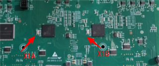
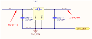
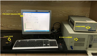
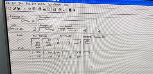
    Today, we came to the TXC factory for crystal oscillator analysis. Among the samples we carried, X1A was in a failed state and X1B was normal; As shown in the following figure:

    1、The positions of the X1A input and output for testing are shown in the figure

    The positions of the X1B input and output for testing are shown in the figure

    From the above picture, it can be seen that X1A is in a failed state, while X1B is normal

    2、Perform blow welding treatment on X1A and X1B, X1A still fails and X1B remains normal;

    Replace X1A, which cannot vibrate, with X1B, and the crystal oscillator will vibrate normally;

    Replace the vibrating X1B with X1A, the crystal oscillator does not vibrate

    3、Remove two crystal oscillators and conduct separate crystal parameter testing. Both oscillators are normal and the parameters are within the error range of the oscillators;

    4、Then, we tested the negative impedance, driving current, and driving power of the crystal oscillator. The negative impedance was greater than 270 Ω (ESR=40 Ω), the driving current was 3.35mA, and the driving power DL=DL=I ^ 2 * (C0/CL+1) ^ 2 * Rr)=69.95uW;

     5、At this point, both the 3.3V and 1.2V voltages of DSP28377D are normal, but the peak value of the crystal oscillator has reached 3.6V or even 3.8V;

    6、Without replacing the DSP and crystal oscillator, compared to the peak waveform of the crystal oscillator a few years ago, the peak voltage of the crystal oscillator was still 2.6V, but now it has reached 3.8V;


    Finally, could you please answer the following questions

    Question 1:Can new conclusions and solutions be drawn by combining crystal oscillator testing with TI's DSP failure analysis report?

    Question 2:As this crystal oscillator is a passive component, is there a register inside the DSP to adjust the amplitude size? If not, is it because of some unknown factors inside the DSP that caused the amplitude to be too large, resulting in EOS damage?

    Regards,

    Hui

  • Hi Hui,

    The 3.6 to 3.8v increase in amplitude on crystal input is concerning as it violates the input spec, which should not exceed 3.3V VDDIO.  As you stated, XTAL is passive component and there is no register in the device that would limit the clock amplitude.  Moreover the pierce oscillator circuit that is used in the F28379x device has a drive level of up to 1mW so so it should be able to supply the power required by XTAL.

    Has there been a change in the XTAL or capacitor BOM from when you started the project a few years back?

    Thanks and regards,

    Joseph

  • There is no  change in the project.As you see, the VDDIO is not exceed 3.3V.Even if the crystal oscillator and capacitor are replaced, the measured waveform peak should not exceed 3.3V. We are in Shenzhen, China, do you have a colleague who can help take a look?

  • Checking with our quality team who can work with you in Shenzhen region.