
- Ask a related questionWhat is a related question?A related question is a question created from another question. When the related question is created, it will be automatically linked to the original question.

art Number: TMS320F2800157
Tool/software:
Total CCStudio-Theia newbie here, so, sorry in advance if this is a dumb question!
I'm designing a system from scratch (not using a pre-made devkit) and used the stand-alone CCStudio to map-out my I/Os, and then created my schematic and layed-out the PCB (which is in fab right now). CCStudio did not show any sort of pin conflicts with the signals I was mapping (I'm using the 48-pin version of the IC, not that that should matter). I'm now I'm starting to write the software in CCStudio-Theia (started with the "Empty 48pin" example) and saw that the SysConfig tool within it had both "Software" and "Reserve Peripherals" sections, which were blank. I figured that I could take the .syscfg file originally created by the stand-alone tool and copy it into the folder of the code project, and magically my assignments showed-up in the "Reserve Peripherals" section. I then searched-around and found-out that "Reserve Peripherals" is for creating your own device drivers/handlers, and the "Software" area is for using the auto-generated drivers/handlers that experts wrote :-) So I figured I'd just re-do all of the configs into "Software" and then delete them from "Reserve Peripherals".
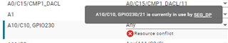
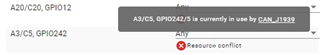
Well, now "Software" is showing a bunch of conflicts between various pins/ports. For instance, in the "Analog PinMux" section it is showing conflicts on pins/ports I've mapped to GPIOs or CAN pins, but I don't see any way to tell it I don't want to use them as an analog pin. I have 10 of these sorts of errors:
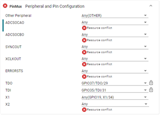
Similarly there are errors in the "Other" section where I need to define the ports (TDI, TDO) being used for the JTAG connector:
In case it helps, here's the spreadsheet I'd created (alongside using the stand-alone SysConfig tool) to map-out my I/Os, as well as the .syscfg file I'm using within CCStudio:
Many thanks (in advance) for whatever help/advise you can give me. And please (please) don't tell me that I've got an issue wherein I need to redesign my mapping and re-lay-out the PCB :-o


