This thread has been locked.

If you have a related question, please click the "Ask a related question" button in the top right corner. The newly created question will be automatically linked to this question.

TMS320F28P550SJ: Configurable Logic Block (CLB) - How do I get started?

Other Parts Discussed in Thread: C2000WARE, SYSCONFIG

Tool/software:

Hello, engineers
Now I plan to use CLB to implement the t-format protocol, look at the 28p55 datasheet, C2000Ware_MotorControl tformat_f28p65x_comms_demo, found very difficult to understand and use directly.


The documents in the following links are also invalid, I would like to get some help.
https://e2e.ti.com/support/microcontrollers/c2000-microcontrollers-group/c2000/f/c2000-microcontrollers-forum/1007238/faq-configurable-logic-block-clb---how-do-i-get-started


There are two other questions:

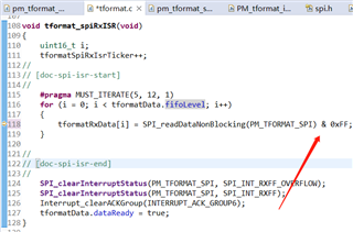
1. In the tformat_f28p65x_comms_demo routine, does CLB only control the direction of RS485? And after receiving the data returned by the encoder, is it first input to the CLB, and then the CLK that the CLB determines to the falling edge and then outputs the SPI?
2. There is no CLB library of 28p55 in the C2000Ware_MotorControl library, is the CLB library of 28p65 common to 28p55?

  • Hi Lin,

    Could you direct me to where the example exists in the motor control sdk? I am not very familiar with the motor control sdk but I can answer your questions related to CLB.

    Thank you,

    Luke

  • Hello Luke,
    Of course, there is no problem. The tformat example directory is in C2000Ware_MotorControl_SDK _5_ 03 _00_In 00\libraries\position_sensing\tformat. Today, I will learn and sort out the issues related to CLB and sincerely ask you for advice.
    Thank you,
    Lin

  • Hi Luke,
    I took a look at the routines today and have a few questions I'd like to sincerely ask:
    1. If I use CLB's tformat routine and the C2000Ware_MotorControl_SDK _5_ 03 _00_In 00\libraries\position_sensing\tformat library to communicate, How do I port it to my existing project? (There was no.sysconfig file in my original project)
    If I don't use CLB's tformat routine and just need CLB to generate SPI_CLK when sending data and receiving data back from the encoder, how should I configure it?

    In the tformat routine:
    1. In tformat.c, when receiving data, why only take the lower 8 bits of the data in SPI_RXFIFO? Just follow the routine to receive the 16bit must be out of place?

    In pm_tformat_source.c, why do we need to send 0xFFFF twice more?


    Looking forward to your reply
    Thank you,
    Lin

  • If I don't use CLB's tformat routine and just need CLB to generate SPI_CLK when sending data and receiving data back from the encoder, how should I configure it?

    The role of the CLB is documented in the design guide (www.ti.com/lit/tidue74)- section 2.3.6: CLB T-format implementation details. In the TI design it is responsible for more than just clocking the SPI.  If you only want it to generate a clock, then the example can be used as a reference.

    1. If I use CLB's tformat routine and the C2000Ware_MotorControl_SDK _5_ 03 _00_In 00\libraries\position_sensing\tformat library to communicate, How do I port it to my existing project? (There was no.sysconfig file in my original project)

    The T-format SW guide has a section on library integration into an existing project once you add syscfg as detailed in the link you found.

    1. In tformat.c, when receiving data, why only take the lower 8 bits of the data in SPI_RXFIFO? Just follow the routine to receive the 16bit must be out of place?

    This has to do with the FIFO width (word size) defined along with the number of bits within a T-format field. The mask makes sure only the needed bits are used in the decoding of the response. 

    In pm_tformat_source.c, why do we need to send 0xFFFF twice more?

    This is to hold the SPI TX high while the RX is being received. I recall this is part of the protocol. It's been a while since I looked at it closely.

  • Hi Lori,
    Thank you very much for your detailed answer, but I encountered problems with syscfg not being able to add and configure properly during the process:

    1、My CCS version is 12.8.1.And I after following the 5 Enabling CLB Tool in Existing DriverLib Projects in the CLB_TOOL_USER's Guide, I encountered the following issues:

    Add the "empty.syscfg" file (C2000Ware_5_04_00_00\driverlib\f28p65x\examples\c28x\clb\empty.syscfg) from the CLB examples folder to the project by copying the file into the project directory.However, CCS did not ask me if I enabled SysConfig.
    Double click to open "empty.syscfg",there will be an error:
    Error loading "xxxxxxx\28P650DK9_Board_cpu1\Release\syscfg" does not exist

    If I click on the blank space, I will enter the interface to select the chip model.

    2、I tried using pm_tformat_f28p65x.syscfg and creat new file named 28P65_Board_cpu1_syscfg, and the same thing happened.
    I want to use the CLB design in PM_tformat_f28p65x_lib,and I start with a new CLB Tile and configure it completely according to pm_tformat_f28p65x.syscfg in my project's syscfg.
    However,after saving syscfg,when i opened the syscfg file again,I was back at the chip model selection interface.

    3、I looked up other information and found that one engineer compiled the PM_tformat_f28p65x_lib project directly, and then added the clbconfig.c and .h files to the previous project for use. Is this how it should be used?

  • Hi Lori,
    I have another question, can I directly use PM_tformat_f28p65x_lib in my original 28p65 project after compiling? How do I add it and use it?

  • 3、I looked up other information and found that one engineer compiled the PM_tformat_f28p65x_lib project directly, and then added the clbconfig.c and .h files to the previous project for use. Is this how it should be used?

    Yes, you can use the library similar to how the communications demonstration uses it.

    Library: All of the CLB logic and support functions are in the library.

    Communications demo project: For connections into/outof the CLB tiles, the logic is in the communication demonstration project sysconfig

    I have another question, can I directly use PM_tformat_f28p65x_lib in my original 28p65 project after compiling? How do I add it and use it?

    If you make any changes to the library C-code or CLB configuration, then the library would need to be recompiled to incorporate the changes. If you do not require any changes, then the library can be used as it is provided.   

    The Library integration section of the SW guide has more information. 

    I will look into the issue you are having with sysconfig and respond back. 

  • Double click to open "empty.syscfg",there will be an error:
    Error loading "xxxxxxx\28P650DK9_Board_cpu1\Release\syscfg" does not exist

    Is the directory shown where you expect the file?  Make sure there are no spaces in the path - I have seen issues with this in the past.

  • Yes,I checked the file directory and there are no spaces.

    Also, I found CLB_Init() in tformat_lib and CLB_Init() in tformat_f28p65_comms_demo. Which one should I use for my project? In other words, it should be tformat_lib or tformat_f28p65_comms_demo's board.c.h file. Which should I use?

  • Also, I found CLB_Init() in tformat_lib and CLB_Init() in tformat_f28p65_comms_demo. Which one should I use for my project? In other words, it should be tformat_lib or tformat_f28p65_comms_demo's board.c.h file. Which should I use?

    Both contain content used by the demo:

    • Library project: All of the CLB logic and support functions are in the library sysconfig --> board.c
    • Communications demo project: For connections into/outof the CLB tiles, the logic is in the communication demonstration project sysconfig --> board.c
  • Thank you very much for your reply.
    I would also like to ask if 28p55 can use pm_tformat_f28p65x? When will 28p55 sample programs be available?

  • The 28P55 has 2 CLB tiles instead of 4. You will need to move the design from tiles 4 & 5 (P65) to 1 & 2 (P55) and change the SPI module to match. (specific tiles can directly connect to specific peripheral instances). If I recall correctly, tile 2 can interface to SPI-B.

    Also - the CPU clock is different so change the scale factor to generate the required encoder clock frequency.  This is detailed in the solution's header file. 

    I have a goal to get a 55x port into the SDK by mid year. 

    Regards

    Lori

  • Thank you very much for your detailed and serious reply,Lori.

    We currently only have one 28p65 PCB board.The external crystal oscillator is 25MHz.We can't use spid in hardware,but we can use spic.So I modified the definition of pm_spi_base in tformat_f28p65_comms_demo,changing it from spid to spic.In the sysconfig of tformat_f28p65_comms_demo,I modified the GPIO of clb_outputxbar,inputxbar and outputxbar:

    • GPIO71 SPIC_CLK

    • GPIO70 SPIC_POCI

    • GPIO72 SPIC_PTE

    • GPIO69 SPIC_PICO

    • GPIO75 RS485_TxEn

    Then in the sysconfig of tformat_lib,I modified clb4 to clb3,and recompiled both projects.

    • However,after burning to flash and running,clb did not work properly,and RS485_TxEn did not change either.Could you please introduce in a bit more detail how I should make the modifications?

    • When sending ID0,there is output on SPIC_PICO,but the data and frequency are incorrect.I checked the function SPI_setConfig in tformat_f28p65_comms_demo,and I wonder why spi_BitRate is 500000.If the system clock is 200MHz and lspclk is 50MHz,then spi_BRR would be 99.According to the manual,the communication frequency of tformat is 2.5MHz.50M/(19+1)=2.5M,so BRR should be 19,right?

    These may be the last two problems I've encountered regarding clb_tformat.

    Regard

    Lin Haonan

  • Let me look into the specifics and I will get back to you within a day. 

  • Hello, Lori,

    I apologize for overwhelming you with so many questions. I truly appreciate your prompt assistance.

    Over the past few days, I've been troubleshooting an issue. After running the functions PM_tformat_setupCommandReadoutReset() and PM_tformat_startOperation(), I waited for several seconds to ensure that the SPI had enough time to complete the DATA_ID0 command transmission. However, I noticed that the TXFFST in the SPIFFTX register remained at 0x1100 and did not decrease. Additionally, I used a logic analyzer to capture the SPI_POCI and TxEn signals but observed no data changes. Based on these findings, I concluded that the CLB is not functioning as expected. It is not generating the SPI_CLK or controlling the TxEn signal, which is preventing the SPI slave from transmitting data properly.

    Thank you again for your support.

    Best regards,

    Lin Haonan

  • RS485_TxEn did not change

    Refer to Figure 2-10, Input/Output and CLB usage for P65x. In the provided example:

    TxEN --> Tile 4 OUTLUT4 --> CLB_OUTPUTXBAR2 --> GPIO1. You will need to change this to accommodate GPIO75. It will be

    TxEN --> Tile X OUTLUT4 --> CLB_OUTPUTXBAR8 --> GPIO75  Where TileX is where you moved the contents of Tile4

    Next check the other INPUT/OUTPUT connections, including those between tiles, to make sure they comprehend the changes you made.

    why spi_BitRate is 500000
    The external crystal oscillator is 25MHz.

    The SPI is in Peripheral mode and is being clocked by the CLB. The BitRate is actually not used in this configuration.

    The SPI clock frequency is determined by the CLB clock rate set in /solutions/boostxl_posmgr/shared/include/tformat.h

    For the given example, the CLB is clocked at 100MHz. I suspect with the changes to your OSC, the device is not clocked at 200MHz (resulting in a CLB clock of 100 MHz). You can use syscfg to help with this. If you do use syscfg then remove the device.c and device.h that are supplied with the example and use the ones generated by syscfg instead. 

    Refer to SW guide 

  • However, I noticed that the TXFFST in the SPIFFTX register remained at 0x1100 and did not decrease.
    It is not generating the SPI_CLK or controlling the TxEn signal, which is preventing the SPI slave from transmitting data properly.

    Yes - good debug. I think this is due to changes in the the tile input/output connections to pin (mentioned in my last post)

  • Hello Lori,

    Thank you very much for your response.However,we are currently on vacation for approximately ten days.I will check it promptly upon my return.Could you please help to keep this post intact?I truly appreciate your assistance.

    Best regards,

    Lin Haonan

  • Hope you have a great vacation. If the system automatically closes the thread while you are gone, click "ask a related question" to start a new post linked to this one. 

    Regards

    Lori

  • Hello, Lori,

    my vacation has just ended, and I'm glad to see this post is still here.

    Today, I checked the INPUT and OUTPUT related to CLB and SPI and found that I forgot to modify XBAR_OUT_MUX28_CLB4_OUT4 in the XBAR_setOutputMuxConfig function and the original CLB4 in PM_TFORMAT_RX_CRC.

    Surprisingly, the communication became normal after these modifications, but the communication rate doubled the expected value (5Mbps, sysclk=150M, TFORMAT_CLB_CLK=75M, TFORMAT_BUS_CLK=2.5M). Therefore, I changed TFORMAT_CLB_CLK to 150M.

      1. Should TFORMAT_CLB_CLK actually be sysclk/2?

      2. Currently, there are no issues with SPI transmission and encoder data return, but I have encountered a problem with SPI data reception errors.

    ① When sending DataID0, I checked the first few groups of data in SPIRXBUF and found the received data to be 0xFFE4, 0x0812, 0x5EBA, etc.Converted to binary, they are 1111111111100100, 0000100000010010, 0101111010111010 ......

    ② When sending DataID3, I checked the first few groups of data in SPIRXBUF and found the received data to be 0xFFE5, 0x8812, 0x34BA, etc.Converted to binary, they are 1111111111100101, 1000100000010010, 0011010010111010 ......

    Inoticed that SPI started receiving data prematurely, with an extra 11 bits of high level received. I speculate that during the encoder's response time, the SPI clk continued to generate, leading to this issue. I then measured the encoder's response time to commands, which was approximately 2.9us, equivalent to 2.9us/400ns=7.25bits, which does not match the actual situation. I would like to ask about the causes of this situation and possible solutions?

  • but the communication rate doubled the expected value (5Mbps, sysclk=150M, TFORMAT_CLB_CLK=75M, TFORMAT_BUS_CLK=2.5M). Therefore, I changed TFORMAT_CLB_CLK to 150M.

      1. Should TFORMAT_CLB_CLK actually be sysclk/2?

    On the P65x, the CLB can be clocked either from the ePWM clock or from the AUXPLL.

    If you have configured the device for SYSCLK = 150 MHz and ePWM = 150 MHz then CLBCLK will also be 150 MHz.

    Side note

    Some older devices have a limitation of ePWM < 100 MHz. This is probably why there is /2 in the example. P65X does not have this limitation.

  • Inoticed that SPI started receiving data prematurely, with an extra 11 bits of high level received. I speculate that during the encoder's response time, the SPI clk continued to generate, leading to this issue. I then measured the encoder's response time to commands, which was approximately 2.9us, equivalent to 2.9us/400ns=7.25bits, which does not match the actual situation. I would like to ask about the causes of this situation and possible solutions?

    Can you capture the waveforms for the request/response like the examples below?

    Does the SW complain about a CRC error?

  • Hello Lori,

    I used logic analyzer to grab SPI_CLK, TxEn, SOMI and SIMO, and used DATA ID 2 for communication test. The waveform diagram is shown below:

    SPI_CLK is correct in the waiting time for the encoder to respond to DATA ID. The data returned by the encoder and the communication timing are correct. But SPI_CLK does have a problem with an extra low level of 1.97us.

    In my application, tformat communication occurs every 62.5us, read out SPIRXBUF DATA and unpack, and send DATA ID after completion the above low level occurrence period is also close to 62.5us. And the SW complain about a CRC error.

    Observe and decode the waveform, and the data returned by the encoder is 0x49 0x04 0xE8 0xA5, which corresponds to the 23bit Tamagawa encoder I used.
    Check SPIRXBUF and tformatRxData separately:

    SPIRXBUF   tformatRxData
    0xFFE4 228(0xE4)
    0x9812 18(0x12)
    0xE8A9 169(0xA9)
    0xE248 72(0x48)
    0xE248 72(0x48)

    There's nothing wrong with looking at time series this way.

    Regards,

    Lin Haonan

  • Hi Lin,

    Seems the waveform is correct as is the received data? But the CRC is not correct?

    The CRC is calculated by a CLB tile as the message is received. I suggest double checking the configuration of the input/output from the CRC generation tile. 

    -Lori

  • Hi Lori,

    Over the past two days, I have carried out a comprehensive examination and reflection on the CLB design. Eventually, I discovered that in the tformat_f28p65x_comms_demo project, the SPI data width is configured as 16 bits. However, according to the communication design, it should be 10 bits. After my modification, the tformat communication returned to normal.

    I have two question regarding this.

    1.In the PM_TFORMAT_CLB_init function within board.c, why is it necessary to configure the GolbalInputMux as CLB_GLOBAL_IN_MUX_EPWM1A?

    2.Why did I cleverly avoid the start and end bits after changing the SPI data bit width to 10bit? See that the received data directly does not contain start and stop bits. It's amazing.

    Moreover, I would like to ask where the Endat - related routines and relevant documents are in the CLB examples. I couldn't find them in the MotorControl_SDK_5.03.

    I'm truly grateful for your timely replies and assistance these days. Sincerely appreciate it.

    Best regards,

    Lin Haonan


  • Over the past two days, I have carried out a comprehensive examination and reflection on the CLB design. Eventually, I discovered that in the tformat_f28p65x_comms_demo project, the SPI data width is configured as 16 bits. However, according to the communication design, it should be 10 bits. After my modification, the tformat communication returned to normal.

    Lin,

    I'm glad that you found the issue. Looks like the code in the SDK has its own SPI configuration as part of PM_tformat_setupPeriph() and doesn't use syscfg for that peripheral. I see how that can be confusing. 

    1.In the PM_TFORMAT_CLB_init function within board.c, why is it necessary to configure the GolbalInputMux as CLB_GLOBAL_IN_MUX_EPWM1A?

    Some of the code in the CLB_init is not required - it is just the default setting for that register. For example, input 0 setting the line to GP_REG (hilighted) takes priority over any local or global input setting.  The global setting isn't used in this case, but the CLB tool/syscfg still issues the code to set it to the default value.

    2.Why did I cleverly avoid the start and end bits after changing the SPI data bit width to 10bit? See that the received data directly does not contain start and stop bits. It's amazing.

    I'll need to go back and look at the code to remember how I did this. It's been a while since I looked at that code. 

    Moreover, I would like to ask where the Endat - related routines and relevant documents are in the CLB examples. I couldn't find them in the MotorControl_SDK_5.03.

    Unfortunately our EnDat2.2 solution was never released into the SDK and the CLB portion was not documented. 

    I'm truly grateful for your timely replies and assistance these days. Sincerely appreciate it.

    Very glad that I could help! 

  • 2.Why did I cleverly avoid the start and end bits after changing the SPI data bit width to 10bit? See that the received data directly does not contain start and stop bits. It's amazing.

    I'm surprised it didn't get documented ... if I recall the alignment in the FIFO is like what is shown below. 

    When the data is read out of the FIFO, in the SPI ISR, it is masked with 0xFF to get the low 8 bits only.

    X S 1 2 3 4 5 6 7 8     <- 10 bits, X is a don't care, S is first start bit

    D S 1 2 3 4 5 6 7 8     <- 10 bits, D is previous delimiter bit, S is new start bit

    D S .. etc