This thread has been locked.

If you have a related question, please click the "Ask a related question" button in the top right corner. The newly created question will be automatically linked to this question.

TMS320F280025C: HAL SENSOR SEQUENCE AUTOMATIC IDENTIFICATION DURING COMMISSIONING


Tool/software:

Hi,

As part of taking my e Bike BLDC Motor controller to  production, during commisioning of one type of motor , would like controller to identify the Hall sensor (A, B or C ) Sequence ...

That is once motor phase wire and hall feedback wires are conected in any sequence, once I run the sequence identification routine, it should identify  which iinput is HALL A, Which one is Hall B and which one is HALL C even if they are not connected in a proper sequence.

Please suggest how to do this  in universal motor controller project.

Thanks in advance.

Regards,

Anil

  • Anil,

    I'd say there are 2 relatively simple options here, neither of which is built into the Universal Motor Control Lab, if I recall correctly.

    1. If you are also using another estimator, such as InstaSPIN-FOC FAST, then you could compare the phase currents to the HALL sensors. Whichever phase current is >0 for the greatest percentage of each HALL input's on-time should correspond to that input, assuming that the sensor and the estimator are operating with approximately equivalent phase delay.
      1. e.g. if you have a hall input (HALL_x), while the motor is running with the FAST estimator, look at the state of the input. Let's say that I_A > 0 for 40% of the time that HALL_x = 1, I_B >0 for 50% of the time, and I_C >0 for 90% of the time. This would tell us that HALL_x is probably HALL_C.
      2. Note that these numbers don't correspond to actual experiments, and are just for example purposes.

    2. If you don't want to use another estimator, then the other simple option would be to run the motor in open loop. While the motor is running in open loop, track the open loop motor position. There are 6 possible orders of HALL_x, HALL_y, and HALL_z. For each configuration, determine if the HALL algorithm correctly matches the motor position. Whichever order results in an estimated motor position that most closely matches the open loop generated motor position should therefore be correct.
      1. Essentially, this would have you test if (for example) HALL_{x,y,z} = HALL{A,B,C} for a period of time, maybe a couple seconds at most should be enough. During this time, determine the average difference between angleHALL_rad and angleGen_rad. Record this, and then repeat the same test, except this time with HALL_{x,y,z} = HALL{A,C,B}. Once you have all six possible configurations recorded, whichever has the lowest average difference should be the correct configuration.

    I hope that makes sense!


    Regards,
    Jason Osborn

  • Thanks Jason for the suggestions..

    I could use a very simple method and find the connected hall sequence and phase sequence from code itself.

    Used MOTOR_ALIGNMENT state with increased  alignment  time.

    For   obj->angleFOC_rad = 0.0; looked at hall state. then changed  obj->angleFOC_rad =  1.0, looked at hall state.

    From above 2 hall state values, could decode and  find HALL U is connected to which pin, HALL V is connected to which pin and  HALL W is connected to which pin.

    Next working on HALL_CAL and then Motor paramter Rs, LS identification from code itself.  This is needed during commisioning  in field. I have a GPIO (CALIBRATION)  for these calibration. When that GPIO is high during power up, one by one firmware will get into

    1. HALL/Phase wire Sequence identification

    2. HALL_CAL

    3. Motor Rs, Ls calcualtion

    4. Above 3 parameters are then stored into  on chip FLASH/EEPROM. Next time during power up, values are taken from EEPROM and used.

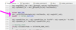
    Working on HALL_CAL next ( SN 2 above) .  One issue I am seeing  is HALL_CAL is a build option. I need to call  HALL_CAL from my normal running program. Any suggestions to make HALL_CAL as a standard  part of the program  and call it whenever CALIBRATION  GPIO is high.

    Is it enough to call "HALL_calibrateIndexAngle(obj->hallHandle, obj->angleEST_rad);" whenever CALIBRATION  GPIO is high. Then write a code to ''' Copy hall_M1.thetaCalBuf[] to hallAngleBuf[]  '''    as mentioned in  motor1_drive.c ..

    Since during HALL_CAL time, need to run in FAST mode only,  how do I change FAST+HALL mode  to FAST mode only and then after HALL_CAL go back to FAST+HAL  from code itself? 

    Thanks & Regards,

    Anil

  • Anil,

    In the FOC loop, control of the motor angle information is handled by "estimatorMode" which you can see in the screenshot you provided. When estimatorMode = ESTIMATOR_MODE_FAST, then the FOC loop uses the motor angle provided by the FAST estimator. When estimatorMode = ESTIMATOR_MODE_HALL, then the FOC loop uses the motor angle provided by HALL. Manipulating this variable allows you to switch which estimator method has control.

    If you want HALL_CALL to be part of your standard operating loop, then I would suggest that any time this code appears inside a function, replace it with something along the lines of "if(HALL_cal_GPIO_state == 1){" and "}", respectively:

    • #ifdef HALL_CAL
    • #endif // HALL_CAL (or similar)

    Any this this code appears outside of a function, just comment out these lines.

    Please note that by default, the code is written with the assumption that HALL calibration is only performed once, then the code is re-compiled with the predefined symbol removed. While I do not see anywhere this could severely impact performance, note that the size of the code will necessarily increase if you do this, and it's possible that I missed something. I would highly recommend testing this thoroughly.

    Regards.
    Jason Osborn

  • This is done, Jason. Thanks for your help.

    Next , I am trying to write these calibration parameters into EEPROM ( in the  FLASH of micro controller)  so that during next power up values can be taken from Flash and use.

    Do you have any any example EEPROM ( internal Flash)  write and read programs  that I can refer ?

    Regards,

    Anil

  • Yes. Refer to the 'flash' folder of Driverlib examples.

    Please note that if you have additional follow-up questions regarding implementation on read/write of the flash, I would ask that you make a new thread so that we can ensure the correct expert is assigned.

    Regards,
    Jason Osborn

  • I have opened a new thread for Flash write related discussion.

    Thanks Jason..

    Regards,

    Anil