Help in defining my BLDC Hub Motor parameters in Universal Motor Control Lab Project

Other Parts Discussed in Thread: DRV8353RS-EVM, DRV8353, DRV8300U

Hi,

I am testing/developing   firmware   with DRV8353RS-EVM + LaunchXL- F280025C for my 2 wheeler BLDC Hub motor referring Universal Motor Control Lab.  Testing with eval board in parallel, while my productiopn board is getting ready which can support higher current than DRV8353RS-EVM.

Please help in defining Motor related parameters in user_mtr1.h file.

I am modifying the default Teknic_M2310PLN04K section in .h file.

My Motor is a 2 wheeler BLDC hub motor . Unfortunately motor datasheet has only below information about motor electrical parameter.

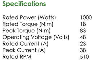
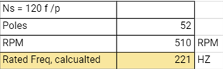
By shorting  2 phase wires and rotating shaft by hand, could find number of poles are 52.

Calcualted rated Freq as below 

Please see the table below where I tried to fill the  motor parameters needed  in user_mtr1.h file. Please suggest the new parameters to  be put  for this motor

SN #if (USER_MOTOR1 == Teknic_M2310PLN04K) HUB MOTOR emfbl-10-48-1000-510
1 #define USER_MOTOR1_TYPE MOTOR_TYPE_PM
2 #define USER_MOTOR1_NUM_POLE_PAIRS (4) 26
3 #define USER_MOTOR1_Rr_Ohm (NULL)
4 #define USER_MOTOR1_Rs_Ohm (0.393955578f)
5 #define USER_MOTOR1_Ls_d_H (0.000190442806f)
6 #define USER_MOTOR1_Ls_q_H (0.000190442806f)
7 #define USER_MOTOR1_RATED_FLUX_VpHz (0.0399353318f)
8 #define USER_MOTOR1_MAGNETIZING_CURRENT_A (NULL)
9 #define USER_MOTOR1_RES_EST_CURRENT_A (1.5f)
10 #define USER_MOTOR1_IND_EST_CURRENT_A (-1.0f)
11 #define USER_MOTOR1_MAX_CURRENT_A (6.6f) 23 (Shall I enter now 15 ? Eval board limitation)
12 #define USER_MOTOR1_FLUX_EXC_FREQ_Hz (60.0f)
13 #define USER_MOTOR1_INERTIA_Kgm2 (7.06154e-06)
14 #define USER_MOTOR1_RATED_VOLTAGE_V (24.0f) // V 48
15 #define USER_MOTOR1_FREQ_MIN_Hz (9.0f) // Hz
16 #define USER_MOTOR1_FREQ_MAX_Hz (600.0f) // Hz 221
16 #define USER_MOTOR1_FREQ_LOW_Hz (5.0f) // Hz
19 #define USER_MOTOR1_FREQ_HIGH_Hz (400.0f) // Hz
19 #define USER_MOTOR1_VOLT_MIN_V (1.0f) // Volt
20 #define USER_MOTOR1_VOLT_MAX_V (24.0f) // Volt
21 #define USER_MOTOR1_FORCE_DELTA_A (0.05f) // A
22 #define USER_MOTOR1_ALIGN_DELTA_A (0.01f) // A
23 #define USER_MOTOR1_FLUX_CURRENT_A (0.5f) // A
24 #define USER_MOTOR1_ALIGN_CURRENT_A (1.5f) // A
27 #define USER_MOTOR1_STARTUP_CURRENT_A (3.5f) // A
28 #define USER_MOTOR1_TORQUE_CURRENT_A (3.0f) // A
28 #define USER_MOTOR1_OVER_CURRENT_A (7.5f) // A
29 #define USER_MOTOR1_SPEED_START_Hz (35.0f) // Hz
30 #define USER_MOTOR1_SPEED_FORCE_Hz (30.0f) // Hz
31 #define USER_MOTOR1_ACCEL_START_Hzps (10.0f) // Hz/s
32 #define USER_MOTOR1_ACCEL_MAX_Hzps (20.0f) // Hz/s
33 #define USER_MOTOR1_SPEED_FS_Hz (3.0f) // Hz
34 #define USER_MOTOR1_BRAKE_CURRENT_A (1.0f) // A
35 #define USER_MOTOR1_BRAKE_TIME_DELAY (12000U) // 60s/5ms

Thanks & Regards,

Anil

  • Hi Anil, 

    Thank you for your question and info! 

    Please allow some time this week to look into this matter properly and provide any suggestions.

    Best Regards,

    -Joshua

  • Thanks Joshua,

    Will wait for your suggestions...

    Regards,

    Anil

  • Of course, 

    I will keep you updated. 

    Best Regards, 

    -Joshua

  • Hi Anil, 

    After looking into your inquiry I believe it is best to involve our C2000 team to further this conversation. 

    Please expect another response within the week.

     Best Regards,

    -Joshua

  • Hello Anil,

    You're correct, that's a rather limited selection of information. Are you able to provide the datasheet here for me to glance through?

    In the meantime, I notice the following (keep in mind that user_mtr1.h section for the Teknic motor has more specific value suggestions. I'd recommend glancing through the comments in that section.):

    • USER_MOTOR1_VOLT_MAX_V should be set, in this case, to the at least the rated voltage (48V)
    • USER_MOTOR1_FREQ_HIGH_Hz should also be set to about the rated frequency
    • If you intend to use motor identification, the ..._EST_CURRENT_A parameters should be scaled appropriately, as suggested in the comments in the Teknic motor section.
    • USER_MOTOR1_MAX_CURRENT_A and USER_MOTOR1_OVER_CURRENT_A
      • Ideally, we want to set these in reference to the motor physical parameters. In this case, if your HW has an explicit current limitation, set these values near that limit. Warning: This may cause difficulties with running the motor, including frequent (or possibly even unavoidable) over current faulting. Without getting improved hardware, I'm not certain that can be resolved.
    • The following parameters are fundamental to the process of spinning a motor and very important, but are not present in your data
      • USER_MOTOR1_RATED_FLUX_VpHz
      • USER_MOTOR1_INERTIA_Kgm2
      • USER_MOTOR1_Rs_Ohm --> This is usually provided in every datasheet
      • USER_MOTOR1_Ls_d_H --> This should be provided in every datasheet, but is sometimes missed
      • USER_MOTOR1_Ls_q_H --> This should be provided in every datasheet, but is sometimes missed

    Regards,
    Jason Osborn

  • Thanks Jason for the details.

    Please find attached Hub motor datasheet. Has very limited information. Please go through and comment..EMFi BLDC Hub motor specs.pdf

    Regards,

    Anil

  • Apologies for the brief delay in response.

    That datasheet is interesting- quite a bit of useful information in it that I've often seen left out of motor datasheets, but it's also lacking in the very basics, like pole pairs and resistance. Strange.

    Ideally, you would see identifying information on the motor plate that might have more of this information if it's not present in the specs. If not, I think your best bet is going to be to use the universal motor control lab's Build 4 & setting flag_bypassMotorId to 'true'. This will allow the InstaSPIN-FOC FAST sensorless estimator to run its motor identification routine, giving you some of that basic information.

    Set each of the motor's physical properties to your best approximation of the motor. For example, your motor is rated 48V, 23A. At a glance- and obviously not exact- the Tool_Makita_GFD01 predefined motor is 36V, 25A. Take these values (if they seem reasonable with the motor in front of you) and then run the motor estimation routine.

    The Universal Motor Control Project and Lab User's Guide, Level 4 Incremental Build section, has more information regarding the identification process.

    Regards,
    Jason Osborn

  • HI Jason, 

    Thanks for the details . We  have put motor parameters close to Tool_Makita_GFD01  and tried to run in DMC_Level 2.  

    Motor tried to move a little bit and stopped for Over current , fault LED glows in driver board.

    We read the driver fault registers,  VDS_HC bit is 1, in Fault status Register 1.  

    We found Gate to source short  for Mosfet Q4. (across C8 in driver board).  

    In fact we had similar failures when we tried to run this motor with another board earlier. Bought a 2nd driver board , tested and that is also showing similar failure.

    Please note on same setup we tested a 2.2 Amp BLDC motor. This worked fine upto DMC_Level 4. Performance was very good, inclduing the step response.

    Please suggest how to go about in testing this hub motor  with our DRV8353RS-EVM + LaunchXL- F280025C setup.  I am aware  that our hub motor can go upto 23 Amp with full load and driver board limit is 15 amp. But we are testing in No load.

    Could not find any protection in harwdare for instantaneous  high current.  If motor rotor does not move, can there be a high current and can that cause mosfet /driver IC failure ? 

    (One more information on setup: Have kept  JP2 (USB_VCC to +3v3) jumper of Launchxl open since this was causing  Driver board 3V3 regulator output and LaunchXL 3V3 regulator outputs getting shorted. As of now Driver board 3v3 LDO supplies both the boards. I can feel LDO of driver board getting heated up. Please comment on this too )

    Thanks & Regards,

    Anil

  • Hello Anil,

    Going through your post, there's a few different things here. First, overcurrent fault, and your note that you're uncertain of hardware protection for overcurrent faults. Second, the note on the Q4 short-circuit. Third, the 2.2A BLDC motor performance up to build 4. Fourth, moving forward on testing the hub motor. Finally, disconnecting JP2 and an overheating LDO.

    1)

    The DRV8353RS-EVM has built-in overcurrent protection- in fact, VDS_HC is an indicator for exactly that fault.

    Referring to the datasheet for the DRV835x gate driver located here,

    • Section 8.3.6 Gate Driver Protective Circuits describes the different protective circuits for the device. Specifically, 8.3.6.3 MOSFET VDS Overcurrent Protection (VDS_OCP), 8.3.6.4 VSENSE Overcurrent Protection (SEN_OCP), and 8.3.6.6 Overcurrent Soft Shutdown (OCP Soft) describe the hardware overcurrent protection used by the DRV835x.
      • A VDS_HC fault is an indicator of a VDS_OCP fault in the C high-side MOSFET. Briefly looking at our implementation of the Universal Motor Control Lab, we're using 'DRV8353_LATCHED_SHUTDOWN' mode, or 0b00.

    2)

    The Q4 short-circuit. You mention that the short-circuit was across C8. Is C8 populated? By default, it is not populated, and there are no instructions in the Universal Motor Control Lab user's guide to populate it. The only instructions in the user's guide are to disconnect J1-17 and J1-19 of the DRV8353RS-EVM from the launchpad.

    Here's an excerpt from the DRV8353RS-EVM schematic, available on the product page of ti.com- note that C8 is disconnected.

    3)

    It's good to here that everything was working for the secondary motor. You mention, though, it was working "up to" build 4. Was build 4 working?

    4)

    The first step of advice that I've always received when facing overcurrent faults with no clear cause is to check to see if there is actually an overcurrent condition. The following will be helpful as first steps:

    • A current probe on the W-phase of the motor will allow monitoring of the actual current. Set an oscilloscope to trigger on the edge of the nFault signal, allowing you to see if there truly is an overcurrent condition on that phase of the motor.
    • Monitoring the high and low outputs of the ePWM signal to a single motor phase. Verify that the deadband is operating correctly.

    I recently ran into a similar situation wherein I was seeing no motor movement, but there was an overcurrent fault. In that case, there really was an overcurrent fault- I had to adjust my motor parameters and I got the motor running properly.

    5)

    For high voltage systems, I generally disconnect JP2 as well- while it shouldn't generally cause any problems, it's better to be safe. You mention that you can feel the LDO getting hot- which part of the DRV8353RS-EVM are you referring to? U3?

    Regards,
    Jason Osborn

  • Thanks a lot Jason Osborn  for the detailed reply.

    Sorry for the delayed response.  

    We got our custom board (with higher current rating mosfet, DRV8300UDPWR driver IC  and  INA4181A1IPWR current  sense Amplifier) assembled. Was busy bringing up that board. Thought   custom  board can easily support 23 Amp needed for our Motor  and we can avoid mosfet and driver IC failures we had on Eval board. Even if some component fails, we have better control in repairing it.

    Please see below  with SN 1-5 against  the points you mentioned in your  previous  response.

    1. Thanks for the information >>  built-in overcurrent protection- in fact, VDS_HC is an indicator

    2.  C8 is not populated. We just used C8 pads to connect probe to Mosfet Gate and source

    3. Yes. Small motor Build 4 also worked fine.

    4. By adjusting the motor parameters, we could get  our Motor running last week, in no load, including DMC Level 4.   We are concerned whether mosfet/driver IC will fail again.  Did not do detailed tests on eval board again. Changing Mosfet and driver IC on eval board is very difficult in our lab setup.

    5. OK. We kept JP2 removed. Yes, U3 was getting heated up when  both LDO outputs were getting shorted (with JP2 connected).

    Our custome board,  Tested upto DMC Level 1 and  offsets are  OK. 

    Can you please suggest  whether we need to bypass driver  IC SPI communincation in code ? If  yes, please suggest where exactly in code we need to do that. Any documentation  on that ?

    Since firmware supports only DRV8353RS ,  not DRV8353RH, we are using RS code only.

    Thanks & Regards,

    Anil

  • Anil,

    Based on the results from your previous tests as you described, I would say that it's rather likely that the source of the issues with the previous board was the motor's current draw. You mention you're now using a board which is rated for the correct current, so it seems like you're fine in that regard.

    However, you're now using the DRV8300U instead of the DRV8353, correct? This may require additional customization. Please ensure that all necessary registers and functions of the DRV8300U match with the code you're using. 

    In order to use the RH instead of the RS version, yes, you need to bypass SPI communication.

    Essentially, there's two different ways you can go about doing this.

    1. Change all of the code for the DRV8353RS to remove the SPI communication
    2. Add a new predefined symbol to the code to only enable the parts we want.

    Adding a new symbol is significantly easier.

    1. In project properties, go to 'Manage Configurations...'
      1.  Select 'New...'
      2. Set the name to 'Flash_lib_DRV8353RH_3SC'
      3. Copy settings from Existing Configuration Flash_lib_DRV8353RS_3SC
      4. Select 'OK'
      5. Select 'Apply and close'
    2. Set the active build configuration to the new one you've just created.
    3. In project properties, go to Build/C2000 Compiler/Predefined Symbols 
      1. Select 'add' and type in BSXL8353RH_REVA
      2. Do NOT remove the 8353RS symbol yet! That will make the rest of this process harder. We'll remove that at the end.
    4. Use the CCS C/C++ Search function (Ctrl+H shortcut) and search for the following:

      BSXL8353RS_REVA

    5. At this point, go through the results. Any line which has either of 'SPI' or 'DRVIC' in the name uses the SPI. Ignore any results which have either of these for now. For all other results, add BSXL8353RH_REVA to the list of predefined symbols. Here's one example from hal.c:

      Notice that this just sets the ADC VREF, which has nothing to do with SPI. In this case, we add our new predefined symbol to the list:
    6. Once you've finished this process, there's just a little bit of cleanup.
      1. In hal.h, the third result should look like this:

        Even though this section includes SPI, add the new predefine to the list:

        #elif defined(BSXL8353RS_REVA) || defined(BSXL8353RH_REVA)

        This section is used for a lot more than just the SCI, and leaving the SCI information here doesn't hurt anyone.
      2. Also in hal.h, the seventh or so result should have a whole list of functions, including HAL_enableDRV, HAL_setupGate, HAL_writeDRVData, etc. Make sure that the new predefined symbol is NOT present here. Scroll down- you should very quickly arrive at the following line:

        #elif defined(BSXL8323RH_REVB) || defined(BSXL3PHGAN_REVA)

        Add the new predefine, changing this line to:

        #elif defined(BSXL8323RH_REVB) || defined(BSXL3PHGAN_REVA) || defined(BSXL8353RH_REVA)

      3. Similarly, in hal.c, the very first result should NOT have the new symbol. Instead, add the symbol to the line which references 'BSXL8323RH_REVB'
    7. Finally, we're done. Return to project properties, Build/C2000 Compiler/Predefined Symbols and remove BSXL8353RS_REVA from the list of predefined symbols for our new build configuration.

    I believe that's all of the major steps in the code. Make sure to compile the code at this point and see what errors, if any, you encounter.

    Regards,
    Jason Osborn

  • Hi Jason,

    Thanks a lot for the detailed response you provided.

    Yes. We are using DRV8300U instead of  DRV8353RS. It is a simple PWM driver IC without any communication/Register setting.  

    For current amplification we are using  INA4181A1IPWR .
    We have ensured that in custom board  all the signals on microcontroller side are exactly same as Eval Board with DRV8353RS.  SPI signals are not used.

    We have done complete bring up of all the sections the board.

    With some minor changes (current full scale gain setting, PWM Dead time  change etc  )  in firmware of Existing Configuration with Flash_lib_DRV8353RS_3SC  we are able to run  a SMALL motor (not our Hub motor that we finally need ) with DMC_LEVEL 2. 

    DRV read, write, spi  communication etc  functions in existing codes  are NOT commented now.   Not getting  any error /fault when we run on our board .

    Will  comment these sections in next few days and  look at the performance. ( Is commenting this really needed ? )

    With Level 2, below are the current   and voltage  (motorVars_M1.Irms_A[0] and motorVars_M1.V_V[0] ) waveforms we are getting when seen in GRAPH of CCS. Set Freq is 2 Hz.

    1. Please comment  about the  current and voltage waveform. (current flat region  is not looking like sinusoidal waveform !!! )

    2. Can I try  DMC LEVEL 3  next ?

    3. Btw  with higher set frequency , we were not gettiing good sinusoidal waveform in GRAPH . Looks to be a sampling freq limitation. Is there a way to get  higher samling freq for Graph data ?

    4.  Commenting DRV read, write, spi  communication etc are they really needed ?

    Thanks & Regards,

    Anil

  • Anil,

    1. Refer to the Universal Motor Control Lab User's Guide. How do your waveforms compare to the example waveforms in the Build Level 2 section of the guide? (Hint: They look fine! They would likely be a bit smoother from a DAC output instead of oscilloscope.)
    2. Yes
    3. I would recommend using an oscilloscope connected to a DAC output. See the user's guide.
    4. Based on my understanding, if you leave them in, there should be no issue. However, that would mean that you're spending cycles running unnecessary, meaningless code. Additionally, if there are any further issues, extra code can be a source of clutter when trying to track down the problem.

    Regards,
    Jason Osborn

  • Hi Jason,

    Lot of Good news !!!!

    1. We could run small motor   in all DMC LEVELs (1,2,3,4) in our Board. Works fine

    2. We could run our Hub Motor  in Level 2 & 3. upto 30Hz. beyond that it trips for Over Current.

    Thanks for your support so far...

    Presently  we are looking at solving over current trip with hub motor at speed  above 30Hz.

    1)  I did not fully understand how Over current bit is set.  Since we are not  using DRV8353RS now, how is Over Current found ?

    Could see below section in code which sets OC bit..

    void runMotor1Control(MOTOR_Handle handle)
    {
    MOTOR_Vars_t *obj = (MOTOR_Vars_t *)handle;
    MOTOR_SetVars_t *objSets = (MOTOR_SetVars_t *)(obj->motorSetsHandle);
    USER_Params *objUser = (USER_Params *)(obj->userParamsHandle);

    if(HAL_getPwmEnableStatus(obj->halMtrHandle) == true)
    {
    if(HAL_getMtrTripFaults(obj->halMtrHandle) != 0)

    {
    obj->faultMtrNow.bit.moduleOverCurrent = 1;

    and...

    static inline uint16_t HAL_getMtrTripFaults(HAL_MTR_Handle handle)
    {
    HAL_MTR_Obj *obj = (HAL_MTR_Obj *)handle;
    uint16_t tripFault = 0;

    tripFault = (EPWM_getTripZoneFlagStatus(obj->pwmHandle[0]) &
    (EPWM_TZ_FLAG_OST | EPWM_TZ_FLAG_DCAEVT1 | EPWM_TZ_FLAG_DCAEVT2)) |
    (EPWM_getTripZoneFlagStatus(obj->pwmHandle[1]) &
    (EPWM_TZ_FLAG_OST | EPWM_TZ_FLAG_DCAEVT1 | EPWM_TZ_FLAG_DCAEVT2)) |
    (EPWM_getTripZoneFlagStatus(obj->pwmHandle[2]) &
    (EPWM_TZ_FLAG_OST | EPWM_TZ_FLAG_DCAEVT1 | EPWM_TZ_FLAG_DCAEVT2));

    return(tripFault);
    }

    Could you please explain how  trip fault and  Overcurrent bit is set ?  

    2).  btw we do not have provision for DAC in our custom board. We are working on dumping data through uart and plotting for debugging purpose to get faster sampling than CCS Graph.

    Regards,

    Anil

  • Hello Anil,

    That's great news! Happy to hear that the board is functional.

    OverCurrent is controlled by the state of the ePWM trip zone. If the ePWM is tripped (i.e. disabled), then the overCurrent flag is set. The ePWM trip zone is controlled in two different ways:

    1. If the motor driver trips, the trip-out pin of the motor driver drives one of the two relevant ePWM trip inputs.
    2. If the C2000 comparator subsystem CMPSS detects that the ADC reading of the current has exceeded user-defined limits, then the CMPSS drives one of the two relevant ePWM trip inputs.

    This means that effectively, the OverCurrent bit is an OR of the motor driver's overcurrent trip mechanism and the C2000's overcurrent trip mechanism. These are redundant mechanisms. We provide both in the Universal Motor Control Lab to show usage examples for both concepts.

    In order to determine which of the two mechanisms are being tripped, check the relevant CMPSS module's trip flags. If the CMPSS trip flag has been set, then the overcurrent trip comes from the CMPSS. If it has not, then the overcurrent trip comes from the motor driver.

    As for the DAC, thank you for letting me know. Thankfully, DAC is not critical, as you've seen.

    Regards,
    Jason Osborn

  • Hi Jason,

    Thanks a lot for Over Current Functionality explanation. It is very clear  now, have fixed the limits properly and do not get OC now.

    With Hub Motor, DMC Level 4, could run  with FAST algorithm - (sensorless , without hall ).

    With Hub Motor, Level 4, with MOTOR1_HALL enabled,  motor  NOT running. Could hear some current flowing noise in to the motor winding. Motor does not move.  

    1. Is this because of any Phase /Hall seqeunce issue. I tried swapping 2 of the phase wires. It did not help . Please suggest how to keep the right Phase/hall seqence.

    2. I have NOT  enbaled HALL_CAL  in pre defined Symbols. Is it really needed ?  What exactly is the function of that ?

    Predefined Symbols screenshot  is below...

    Thanks & Regards,

    Anil

  • Anil, I would recommend running HAL Calibration at least once. It is possible that a lack of calibration is related to your motor issues.

    Refer to the following excerpt from motor1_drive.c:

    If you're not using one of the predefined motors listed above, you should be running into a compilation error due to line 195. (It may be a different line for the F28002x, but it should still be present.)

    In order to run the calibration routine, enable MOTOR1_HALL, enable HALL_CAL, and comment out line 195.

    Once you've run the calibration routine, add the following code before line 194, replacing [Motor] with the name of your motor from user_mtr1.h and [Buffer] with the contents of hall_M1.thetaCalBuf after calibration.

    #elif (USER_MOTOR1 == [Motor])
    const float32_t hallAngleBuf[7] = { [Buffer] };

    I would also suggest un-commenting the #error at this time.

    Regards,
    Jason Osborn

    As a side note, the CCS ctrl+h file search option is very useful in determining what a given #define predefine does- often, like the one above, the behavior of the predefine will be explained in the comments of the code.

  • Hi Jason,

    Good news is  able to run Level 4 with HALL feedback.

    Had to input motor inertia right value ( Higher speed Kp was needed ), increase the over current limits .

    HAL_CAL is also done as you suggested.

    Now the  issue is  Motor is making lot of noise with FAST+HALL algorithm where as it is running smoothly with FAST sensorless algorithm.

    Probed HALL signals. they  are very clean.

    Looked at Rotor angle and  Phase A current by using DATALOG + Graph with the following code

    datalogObj->iptr[0] = &motorVars_M1.angleFOC_rad;
    datalogObj->iptr[1] = &motorVars_M1.adcData.I_A.value[0];

    With FAST Alogorithm, getting smooth rotor angle and sinusoidal current.

    WIth HALL + FAST algorithm, current waveform is not sinusoidal. Looks like 2 or 3 pieces of sinusoidal current changing with hall sensor position  changes.

    Looked with  both  + Speed Ref and - Speed Ref. Current waveform is bad.

    We have used    #define USER_M1_SIGN_CURRENT_SF         (-1.0f)   to take care of an invertion in external current sense amplifier.

    Tried with all the 6 combinations of Hall signals. 2 of them it worked.  Getting  bad current signals + noise from motor for both the 2 working hall sensor combinations.. Tried interchanging phase wire too.

    Please suggest what  to look at next.

    Could it be anything to do with  usage of  #define USER_M1_SIGN_CURRENT_SF         (-1.0f)  ?

    Below is the Datalogger graph plot for both FAST algorithm and FAST+HALL algorithm .

    Also, please let me know why in user guide it is shown ,  with FAST+ HALL,  current is sinousidal in FORWARD direction and  non sinusoidal in REVERSE direction.

    Thanks & Regards,

    Anil


  • Anil,

    Glad to hear that the motor is able to run at level 4!

    I'll look into the question regarding the user's guide further, but at a glance, it appears that the yellow signal represents the angle value that's actually being used by the universal lab to control the motor. This means that in the forward direction, they're showing the motor's performance using FAST, and in the backwards direction, they're showing the motor's performance using HALL.

    Because HALL has distinct angle values instead of smooth calculations, performance is going to be visibly worse. In the past, I've seen interpolating the HALL angle value based on the motor's reference speed (from the speed control loop, NOT speedRef_Hz) and the known angle values be successful after the startup process is completed.

    I don't think the waveform you're seeing with HALL is due to USER_M1_SIGN_CURRENT_SF. If that were the case, FAST would also be nonfunctional. At this point, I would use FAST to run the Motor Identification routine on the motor and update the values in user_mtr1.h accordingly. If the values there are far enough from the actual, it could be resulting in incorrect calculations in the ISR.

    Let me know the results once you've done so!

    Regards,
    Jason Osborn

  • Thanks Jason for the details.

    We have done Motor identification as per user guide in FAST mode.  Values are updated in code. Still current waveform is not sinusoidal and we get noise from motor which is not all acceptable for our eBike application.

    I went through some other e2e discussions and could see  someone mentioning with HALL it is a simple 6 step algorithm and current waveform is not sinousidal. 

    Dont we have a HALL + FAST algorithm , in which "interpolating the HALL angle value based on the motor's reference speed "  that you mentioned in previous message ?  

    Btw, I tried changing  estimationmode from HALL to FAST while motor is running and the whole electrical noise is gone. But are we compromising in any performance by not using HALL feedback  after switching to FAST?

    Please suggest how to go about ? Our application(eBike)  needs sinusoidal  current  with HALL so that we get smooth and instantaneous starting.

    Thanks & Regards,

    Anil

  • Anil,

    The Universal Motor Control Lab's HALL + FAST mode does not utilize both at the same time. Instead, it is designed to allow you to dynamically switch between the two estimators at runtime for ease of testing. The Universal Motor Control Lab does not have built-in interpolation of the HALL angle value.

    As for HALL vs FAST, in my personal experience, if your user_mtr1.h physical motor parameters are accurate to the motor you're using , then I've typically seen better performance from FAST than I have from a HALL encoder. This is, of course, just my personal experience.

    For the poor HALL performance, is this true at both high and low speeds? Is it present only during startup, only during normal operation, or both? The answer to these questions will help me diagnose the likely cause of the rest of your issues further.

    Regards,
    Jason Osborn

  • Hi Jason,

    We are getting very smooth performance with FAST. I am only concerned with not so smooth starting. Need to really check whether it will be an issue for eBike Application.

    Noise is there throughout the speed range in HALL mode.

    As of now, proceeding with starting with HALL , chaging to FAST ...

    Using below code (if ...else.... section ) in   while(systemVars.flagEnableSystem == true) section.. Please let me know whether you any issues in this...

    while(systemVars.flagEnableSystem == true)
        {
       // loop while the enable system flag is true
       systemVars.mainLoopCnt++;

    if (motorVars_M1.motorState >= MOTOR_CL_RUNNING)
       {
                  motorVars_M1.estimatorMode = ESTIMATOR_MODE_FAST;
       }
    else if (motorVars_M1.motorState < MOTOR_CL_RUNNING)
       {
                motorVars_M1.estimatorMode = ESTIMATOR_MODE_HALL;
       }

    Regards,

    Anil

  • Anil,

    I would personally put that code in or near the runMotor1Control() function for the sake of consistency, but I don't see any issue with it other than that preference.

    For HALL performance, it may be worthwhile to add GPIO Qualification to the HALL pins if it's not already present, or increasing what's there. These are the relevant Driverlib functions:

    GPIO_setQualificationMode

    GPIO_setQualificationPeriod

    Refer to the device Technical Reference Manual for more details on the usage of these and for how much delay they add when filtering. If noise on the pins continues to be an issue, check to see if you can add a simple RC filter to those pins for external filtering instead (not too large, or the rise time may be significantly impacted)

    Regards,
    Jason Osborn

  • Hi Jason,

    As you suggested moved code within runMotor1Control(). Works fine.

    HALL signals are filtered with RC and the one goes to uC is totally noise free. Have done HAL_CAL too.

    Mine is a 48V/23Amp/220Hz motor. Can you please comment on below parameter values that I have used..

    #define USER_MOTOR1_FLUX_CURRENT_A   15.0
    #define USER_MOTOR1_ALIGN_CURRENT_A    1.5
    #define USER_MOTOR1_STARTUP_CURRENT_A  15.0 

    Flux current should ideally be zero for BLDC motor , I thought ?  what exactly is the purpose of flux current and Align current ?

    Where can I find detailed explanation of the parameter definitions in user_mtr1.h ? Any documents ?

    Btw, we have interfaced Throttle to the code now, running motor from throttle. Works fine. Had to remove some delay  in 

    updateExtCmdPotFreq() so that motor starts immediately if throttle is  made zero and full immediately..

    Regards,

    Anil

  • Anil,

    Thank you for the update. For those parameters, I'll describe them with the assumption that startup is performed with estimatorMode = ESTIMATOR_MODE_HALL. FAST will be very similar, but not necessarily exactly the same.

    Here's a summary table of what I'm about to describe:

    Motor State Id ref Iq ref
    MOTOR_ALIGNMENT Align current 0
    MOTOR_OL_START 0 (Flux current for 1 ISR) Startup current
    MOTOR_CL_RUNNING 0 IsRef_A (output of speed PI controller)
    MOTOR_CTRL_RUN 0 IsRef_A (output of speed PI controller)
    • During startup, the PI controller reference value for Id is set to align current. This is during motor state MOTOR_ALIGNMENT (~2s), after which it is set to flux current as the motor moves to state MOTOR_OL_START.
      • An upcoming release of the Universal Motor Control Lab User's Guide has the following text to describe USER_MOTOR1_ALIGN_CURRENT_A:
        • This parameter defines the current used to run motor rotor alignment, in A. This parameter should be set to 5%-50% of the rated current of the motor.

    • During startup, the PI controller reference value for Id is set to very briefly set to flux current during the transition to motor state MOTOR_OL_START. However, this is nearly instantly overwritten by a value of 0 with the combination of settings used by your project. This value is therefore relevant for exactly 1 ISR. (If FAST were used during startup, it would be used longer.)
      • An upcoming release of the Universal Motor Control Lab User's Guide has the following text to describe USER_MOTOR1_FLUX_CURRENT_A:
        • This parameter defines the current used to run the motor in forced open-loop, in A. This parameter should be set to 5%-50% of the rated current of the motor.
    • During startup, the PI controller reference value for Iq is set to startup current. This is during motor state MOTOR_OL_START
      • An upcoming release of the Universal Motor Control Lab User's Guide has the following text to describe USER_MOTOR1_STARTUP_CURRENT_A:
        • This parameter defines the current, in A, used to run the motor when the speed is below the defined startup speed (USER_MOTOR1_SPEED_START_Hz). This parameter should be set to 10%-100% of the rated motor current.

    If the motor is rated for 23A, align current should be set between ~1A to ~11.5A. Startup current should be set between ~1A to 23A. In my experience, I've usually seen these set around 10-15% of the rated current. For loaded motors, startup in particular will likely need to be higher.

    Regards,
    Jason Osborn

  • HI Jason,

    Your explanation is too good. Start up sequence is very clear to me now. Thanks a lot.

    I am getting around 2 sec delay with both  FAST and HALL modes.

    Decreasing  #define USER_M1_ALIGN_TIME_SET              (2000U) did not help.

    2 sec delay is not acceptable for eBike application. Once throttle is given , within  a few msec, motor should move.

    Is MOTOR_ALIGNMENT needed even with HALL ? Since we already know the hall/rotor position. 

    If it is enabled, is  it possible to disable it in HALL mode ?

    Also, what are the other possible causes  of start up delay with HALL. I am running  from expression window & also tested with  throttle. (throttle is connected at the place of POT pin and CMD_POT_EN is enabled). Getting delay in both the cases.

    Once again, thanks for your support.

    Regards,

    Anil

  • Anil,

    Happy my explanation was helpful! For the purpose of motor alignment, though, I'll leave that to an expert that I myself have learned from:

    If the HALL sensor were an absolute encoder, I believe alignment would not be necessary. However, it is not.

    The biggest notable delays in startup are as follows, as seen in motor1_drive.c:

    • flyingStartTimeDelay, defined in initMotor1CtrlParameters as 0.5 * the ISR frequency in Hz 
      • If you never expect your motor to already be moving when the system starts up, flagEnableFlyingStart can be set to 'false' to bypass this entirely.
    • alignTimeDelay, defined in initMotor1CtrlParameter as 0.1 * the ISR frequency in Hz
    • startupTimeDelay, defined in initMotor1CtrlParameter as 2 * the ISR frequency in Hz

    To adjust, adjust these definitions. I believe they're intended to be defined via the #define parameters in user_mtr1.h, and I'm not sure why they aren't. I'll look into that.

    Regards,
    Jason Osborn

  • Hi Jason,
    Thanks for the detailed explanation on startup possible delays and documents on Alignment related explanation.
    I understood many of it. Still have to learn more.

    Btw, using Datalogger graph, we plotted motor state during start up. In other channel actual speed.

    During starting, states are MOTOR_SEEK_POS = 5 for a short duration, MOTOR_ALIGNMENT= 6 for a longer duration and then moves to MOTOR_CL_RUNNING=9,

    Alignment time is the major contribution in both HALL+FAST mode and FAST mode. Tried decreasing   #define USER_M1_ALIGN_TIME_SET . Did not show any effect. 

    As understood from your explanation and seen in the graph,  with HALL also we are doing alignment to get a smoother start.

    1). Is there a way to test  bypassing alignment in HALL mode. once we get first edge of the hall, rotation should be smooth, right? At least we can test and get a feel of the starting. If  we can bypass, would be good if you can point me to the section in code where I need to make the changes.

    2)  You explained 3 delays as 

    flyingStartTimeDelay = 0.5 * the ISR frequency in Hz
    alignTimeDelay = 0.1 * the ISR frequency in Hz
    startupTimeDelay = 2 * the ISR frequency in Hz

    the ISR Frequency in HZ, Do I have to use   "#define USER_M1_ISR_FREQ_Hz"  ?

    3) Startup Time delay is highest as per above explanation. But I am not getting   MOTOR_OL_START   = 8   state during starting ? Pls explain

    4). Below is the graph captured in Datalogger graph. Can you explain how to calculate actual time from samples. I tried x axis in ms too. Time is not correct.

    Estimator Type : FAST_HALL

    Estimator Mode : HALL

    Regards,

    Anil

  • Anil,

    Based on what I saw in the code of the lab, the #define time delays are currently nonfunctional. Instead, the code (as seen in motor1_drive.c function initMotor1CtrlParameters() ) uses objUser->ctrlFreq_Hz multiplied by a constant to determine the time delay. To change the time delays, change these constants.

    1. If you intend to bypass alignment, navigate to motor1_drive.c function initMotor1CtrlParameters() and change obj->flagEnableAlignment in the section of the code relevant to your system (FAST & HALL). I highly recommend very thorough testing of that solution- whether this is functional will depend, if I recall, very heavily on the motor you're using.
    2. The code uses "objUser->ctrlFreq_Hz" to represent the ISR frequency. objUser->ctrlFreq_Hz is defined as USER_M1_ISR_FREQ_Hz. I recommend changing the constants as I described, not the control/ISR frequency.
    3. Glancing at the code again, it looks like when using HALL, the system remains in MOTOR_OL_START for only 1 ISR. However, referring to the runMotor1Control() function, there are values reliant on startupTimeDelay after entering MOTOR_CL_RUNNING.
    4. The settings described in the Universal Motor Control User's Guide should be generally correct to give approximately real-time data.
      1. Sampling Rate should be updated if the clock speed utilized is not 100MHz.

    Regards,
    Jason Osborn

  • Thanks Jason for all the details... Startup issue is solved by making decreasing alignment time in code.

    In motor1_drive.c changed 

    obj->alignTimeDelay = (uint16_t)(objUser->ctrlFreq_Hz * 2.0f); // 2.0s

    to  

    obj->alignTimeDelay = (uint16_t)(objUser->ctrlFreq_Hz * 0.1f); 

    Now startup is much faster. 

    No need to bypass alignment.

    Planning to start testing on vehicle.

    Will come back with next set of issues for your support :-)

    1. Is putting correct inertia very crical when we test in vehicle. I am planning to put an approx value  of 0.1 kgm2

    2. Do  you recommend to tune Speed loop Kp, Ki on vehicle ?

    Regards,

    Anil

  • Anil,

    I'm happy to hear that issue was resolved!

    1. An accurate inertia value will increase the efficiency of the motor dramatically if your initial value is incorrect.
    2. I would generally recommend tuning the Kp/Ki parameters for PI controllers.

    Regards,
    Jason Osborn

  • Hi  Jason,

    Was busy testing  on 2Wheeler ( e Bike). After some tuning of current, Gain etc, we are getting reasonably good performance. 

    As of now we are getting  good performance with FAST algorithm  itself  and hence HALL is not used as of now.

    Have following 3 issues. Please suggest how to go about.

    1) Flying start is not working OK, (tripping for OC ) at one particular condition.

    That is when motor is running  at some speed, if throttle ( Analog speed ref)  is brought to zero and taken high immediately it trips for OC. At this point motor is already running, flying start should have taken care this.

    Looks like   restartMotorControl(handle); is being called (makes speedAbs_Hz = 0 ) becuase  of objMtr->cmdPot.flagCmdRun = false; and true later immediately, which  makes it to comes out from  flying start condition .

    Looking at the code, felt objMtr->cmdPot.flagCmdRun = false in below section is making 

    if(objMtr->adcData.potAdc <= objMtr->cmdPot.adcMin)
    {
    objMtr->cmdPot.waitTimeCnt++;

    if(objMtr->cmdPot.waitTimeCnt > objMtr->cmdPot.waitTimeSet)
    {
    objMtr->cmdPot.flagCmdRun = false;
    objMtr->cmdPot.speedSet_Hz = 0.0f;
    }

    2.  Even for a single tripping of OC, we need to manually clear fault from expression window to continue the motror to run. Please suggest a code change  so that code will clear the fault and motor will run itself till the number of fault is equal to the number of restart times.

    Could also find a variable  "overCurrentTimesSet" which is not being used. Any plan to add this feature ? Please share if you already have an example code for this.

    3. With flying start enabled, can we get non regenerative braking?.

    With regenerative braking in 2 wheeler application, we do not have free running of wheel when throttle is brought to zero. i.e, instead of a controlled braking/decceleration, a free motor running is prferred  when throttle level is decreased.

    Thanks & regards,

    Anil

  • Hi Anil,

    Jason is out today. Please allow him some extra time to get back to you. Thanks for your understanding.

    Best,

    Kevin

  • Hi Kevin, thanks for the information. 

    Will wait for Jason to be back and for his reply.

    Regards,

    Anil

  • Anil,

    1. That is an interesting interaction of the flying start and cmd potentiometer modes that I was not aware of- thank you for informing us of this! At a glance, I would think that this alteration might help (As always, all suggestions are being made with the understanding that they have not had the opportunity to be tested, and should be thoroughly tested before being implemented in any final end application):
      1. Altering the code excerpt you mentioned from:

        if(objMtr->adcData.potAdc <= objMtr->cmdPot.adcMin)

        to:

        if((objMtr->adcData.potAdc <= objMtr->cmdPot.adcMin) && (objMtr->speed_Hz < objMtr->speedFlyingStart_Hz))

      2. This should ensure that the motor doesn't go into the 'off' condition incorrectly or early in the case of flying start. As for limitations, I see immediately that there's no handling of the cmdPot.waitTimeCnt variable in this suggested implementation- something would also need to be added there. For example, resetting the value as an else case, perhaps?
    2. Simply setting code up to automatically set obj->flagClearFaults after a time delay would allow you to do this. The current implementation is designed solely for a debug scenario, which is why it requires a manual clear.
      1. Note that based on the convention used elsewhere in the project, the 'overCurrentTimesSet' variable would not be a variable to automatically clear the overCurrent fault. Instead, it would delay the activation of the overCurrent fault by a set amount of time. I do not see many use cases for that feature.
    3. I will look into the regenerative braking question and get back to you.

    Regards,
    Jason Osborn

  • Hi Jason,

    Thanks for the details...

    Regarding point 1), I have already tried something similar to the code you mentioned . See code below...

    if(objMtr->adcData.potAdc <= objMtr->cmdPot.adcMin)
    {

    objMtr->cmdPot.speedSet_Hz = 0.0f;
    if(motorVars_M1.speed_Hz <=3.0)
                   objMtr->cmdPot.flagCmdRun = false;
    }

    else
    {
            objMtr->cmdPot.flagCmdRun = true;

    With this , I was able to get the OC not happening during throttle to zero and max immediately after that.

    But  have an issue when we tried to test on vehicle. When throttle is made to zero position, motor decelerates in a controlled rate. With this code when we appy brake  during this decelration time, we have to apply brake against the motor controlled deccelration.  This is not OK for 2W application, we need the wheel to be free at this time and mechanical brake controls when to stop the motor. 

    Is it important to have cmdPot.waitTimeCnt in this case ?

    I have a feel this is in regenerative braking at this time. Please suggest  how to go about.

    Will reply to your comments on 2 later.

    Regards,

    Anil

  • Hi Jason,

    Could you look at the issue I mentioned in previous post ? (copying again here below)

    "But  have an issue when we tried to test on vehicle. When throttle is made to zero position, motor decelerates in a controlled rate. With this code when we appy brake  during this decelration time, we have to apply brake against the motor controlled deccelration.  This is not OK for 2W application, we need the wheel to be free at this time and mechanical brake controls when to stop the motor."

    I was looking for a way to make the torque zero (or very small value)  during stopping when pot adc count less than adc min. This way I feel, once  rider applies mechanical brake, there will not be any opposing force from controller side  and vehicle will be able to stop smoothly.

    Please wee whether below code will do the job.. ( not tested on vehicle yet)

    if(objMtr->adcData.potAdc <= objMtr->cmdPot.adcMin)
    {

    objMtr->cmdPot.speedSet_Hz = 0.0f;
    motorVars_M1.IsSet_A = 0.0f; // 1. to make torque ZERO
    if(motorVars_M1.speed_Hz <=3.0)
    objMtr->cmdPot.flagCmdRun = false;

    }

    else
    {
            motorVars_M1.IsSet_A = USER_MOTOR1_TORQUE_CURRENT_A; // 2. to make torque old value.
            objMtr->cmdPot.flagCmdRun = true;

    Is IsSet_A the variable to control torque ? If not please suggest the right variable to be used.

    Would be helpful if you can reply today itself.

    Regards,

    Anil

  • Anil,

    In build level 4,

    IsSet_A is not the right variable- this is only used when the speed loop is entirely unused in build 4.

    IsRef_A should be the right variable, which is normally set by the speed loop.

    In build level 3, Idq_set_A is the right variable.

    Please let me know if I missed any questions!

    Regards,
    Jason Osborn

  • Thanks Jason.

    My intention is to make torque zero when throttle is made to zero position so that mechnaical brake can control the vehicle to stop.

    Tried the following code. Not working as expected. I tried to plot IsRef_A in graph wrt to pot_ADC. IsRef_A is not becoming zero as soon as  pot_ADC is zero.

    Any suggestion what could be wrong ?

    in motor_common.c >>>>

    if(objMtr->adcData.potAdc <= objMtr->cmdPot.adcMin)
    {

    objMtr->cmdPot.speedSet_Hz = 0.0f;
    still_running = 1;

    if(motorVars_M1.speed_Hz <=3.0)
    objMtr->cmdPot.flagCmdRun = false;
    }

    else
    {
    objMtr->cmdPot.flagCmdRun = true;

    still_running = 0;

    in motor1_drive.c >>>>

    // for switching back speed closed-loop control
    PI_setUi(obj->piHandle_spd, obj->IsRef_A);

    if (still_running == 1)
                  obj->IsRef_A = 0;

    Please see below graph with pot adc (1) and  IsRef_A (2) below.

    2 is becoming zero only after motor stops.

    Regards,

    Anil

  • I believe still_running = 0; is in the wrong section of your if/else statement, per the logic you applied in motor1_drive.c.

    Regards,
    Jason Osborn

  • Hi Jason , 

    still_running = 0 location looks OK.

    Had some board issues and  some other priority. Starting working on this from today. Will update you ...

    Regards,

    Anil

  • Hi Jason,

    Tested on 2 wheeler today.

    1. With the code >>>     if (still_running == 1) ,     obj->IsRef_A = 0;

    There is a reduction in torque when throttle is brought to zero position while running. We are able to stop the motor by applying brake. Still , it is showing some resistance/torque while stopping. Any suggestion whether we should do anything on current loop sode too?

    2. Torque seems to less while starting. Sometimes vehicle needs a slight push to move. Once it moves performance is pretty good.

    Current settings are >>>
                   Alignment current 0.7 amp
                   Starting current 7.5 amp
                   Max current 23 amp

    Thinking of increasing alignment current and starting current .  Will also try increasing speed Kp.  

    What is your suggestion ?

    3. We are using FAST algorithm now ( hall sensor not  used).   For FAST (without hall ), is it SEEK_POS state (not alignment) ?

    What is the current applicable for SEEK_POS state ? Is it alignment current only ?

    Thanks & Regards,

    Anil

  • Anil,

    1. Offhand, I'm not certain what the issue is there. I will get back to you.
    2. Increasing starting current is my initial thought, as well as perhaps increasing the startup acceleration.
    3. SEEK_POS should be the Flying Start motor state, meaning it is not initially applying current. After the Flying Start time delay, it moves to alignment (if the motor is in standstill) or the running state (if the motor is already moving).

    Regards,
    Jason Osborn

  • Hi Jason,

    Was busy in cleaning up the testing, adding some more functions for field trial etc...

    As of now, has one main issue to be sorted out.

          Setup is like below..

                * Brake applied fully

                 * Speed Ref is applied 

    With this,  motor runs at a fixed  low speed,  taking  motor max current  set in the user_mtr1.h. 

    Motor speed displayed is around   -127 Hz ( please note physically motor direction has not changed).

    Now if removbe load, motor does not get back into control. It runs at that low speed taking max current.

    Only way to come out of this is , making speed ref = 0.

    See below expression window screenshot

    Graph A is pot ADC

    Graph B is Speed_Hz

    Can you suggest ,  how do go about in debugging this ?

    Regards,

    Anil

  • Anil,

    I'm not certain what might be causing this. As a primary debug step, I would look at the ADC measurements and alpha/beta or d/q axes measurements to see if anything is visibly off there. I would also look through the values in the PI controllers to see if anything is being fully saturated.

    Regards,
    Jason Osborn