This thread has been locked.

If you have a related question, please click the "Ask a related question" button in the top right corner. The newly created question will be automatically linked to this question.

C2000WARE-MOTORCONTROL-SDK: Follow up - Motor control issues at high current and speed

Part Number: C2000WARE-MOTORCONTROL-SDK
Other Parts Discussed in Thread: MOTORWARE, BOOSTXL-DRV8320RS, DRV8320, LAUNCHXL-F280049C, DRV8323

Tool/software:

Hello,
We would like to follow up on this question, because as it seems, we are facing exactly the same issue as reported in this thread and no adequate answer can be found on the whole forum. 

Recently we made a transition from F28069M (using MotorWare) to 3rd generation processor F280041C (using MCSDK 5.0.0.3) on our motor controller board, designed for high-power application with a low-inductance motor. On the previous version, which uses MotorWare, we’ve successfully run the motor up to 3kW without any issues. Now we are struggling to get higher with RPMs than some point around 9000. To avoid the effect of the speed controller, we also tried torque control mode with the Iq setpoint. We also verified that the output parameters of the identification process are almost identical as with the old version. 


Parameters of the system:
PWM freq. : 20kHz

ISR freq: 20kHz

Current control freq. : 20kHz

Speed control freq. : 2kHz 

Voltage filter pole freq.: 654Hz

Voltage ADC scale: 39.685

Current ADC scale: 825

Max VS mag: 0.5

Identified parameters of the motor:

USER_MOTOR_Rs_Ohm                 0.0110599976

USER_MOTOR_Ls_d_H                 3.74998126e-06

USER_MOTOR_Ls_q_H                 3.74998126e-06

USER_MOTOR_RATED_FLUX_VpHz        0.00662664603

USER_POLE_PAIRS 7


Our observations:
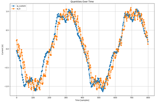
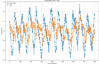
1. Using torque control mode with Iq setpoint higher than 170A, the estimated RPM differs from real measured RPM with external optical sensor. Setting the setpoint higher does not further increase the RPM.

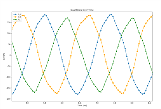
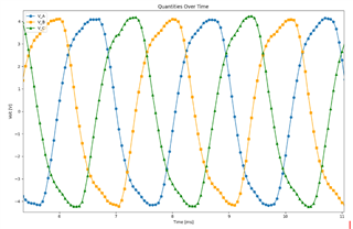
2.Currents and voltages sampled on all three phases look good around the 170A Iq setpoint. But if the setpoint is set higher reaching some point things go crazy and distortion is visible on current and also on angle estimation. The same happens when we try to push RPM higher in speed control mode.


3.Iq current seems to oscillate more than expected (captured in torque control mode with Iq step from 5 to 10A).   
  
We of course also tried to tune PI parameters of the current regulators, but it had no significant effect on oscillations. 

4.There are 3 new parameters in the code, which have significant impact on the system, but there is no adequate definition of them. We would appreciate some information on what these parameters really do in the estimator and how to tune them.


USER_EST_FLUX_HF_SF - increasing this value higher than default 0.125 value, sets the maximum achievable RPM lower. Setting it to value 1, we were not able to reach more than ~7000 RPM. 

USER_EST_FREQ_HF_SF - seems to have no effect

USER_EST_BEMF_HF_SF - has significant impact on RPM estimation. 


It seems that from some reason the MotorControl SDK acts differently from MotorWare in the high power/RPM range and we need to understand why. We decided to move to this new generation of processors with the view of achieving higher performance, unlocking new possibilities and avoiding the obsolescence of older components. However, this has so far led to these issues and delays in delivering our devices to customers on time. We would really appreciate your help. 

  • Hi Tomas,

    It seems that from some reason the MotorControl SDK acts differently from MotorWare in the high power/RPM range and we need to understand why

    Does CPU speed differ in new MCU class? Often number of speed ticks (user.h) can cause odd issues. However, we have found it necessary to tweak (reduce) the inductance Ld/Lq values (manually) until full closed loop trajectory speed is reached. Be sure the motor is actually in closed loop not running open loop! Minor changes Ld/Lq values can achieve a new top speed being clue the inductance is not quite what it should be to run motor rated unloaded speed. Another issue may be caused from the inertia moment, if included in (user.h) the speed PI (Kp/Ki_speed) values can vary greatly. Also check the ADC current & voltage offsets are acceptable via CCS debug motor identify & run script

    Custom board designs should first run isLAB-04 verify all signals are correct as expected by ADC sense code (hal.c/h) and no crossed channels exist causing over current conditions. You may also try the Universal Motor control SDK with the newer MCU classes.  

  • Hello,

    Thank you for your response to Tomas' question (I am his colleague). While we had already addressed these steps in the past, we revisited them to double-check and ensure everything was correctly configured:

    • CPU speed and speed ticks are correctly set for the given processor class.
    • Current and voltage offsets are correct and align with the designed values.
    • We verified the signals using LAB04, and for comparison, we also set up your developer kit LAUNCHXL F280049C with BOOSTXL-DRV8320RS.Phase currentCurrent Iq
    • The speed loop was initially used only in closed-loop mode, but to eliminate any potential issues, we switched to torque control.

    However, we still have a few questions we’d like to clarify:

    1. If it is necessary to reduce the motor's inductance compared to the identified value, why did this not occur when using MotorWare?
    2. What is the role of the parameters USER_EST_FLUX_HF_SF, USER_EST_FREQ_HF_SF, and USER_EST_BEMF_HF_SF in speed estimation and the overall performance of the estimator?
      • During testing, we measured both real (optical probe) and estimated RPM for two different motors ([motor one: max speed ~7kRPM, max power 1kW] and [motor two: max speed ~10kRPM, max power 3kW]) and noticed a discrepancy between the values.
      • By carefully adjusting these parameters, we managed to achieve good alignment for motor one within its operating range.
      • For motor two, however, a significant difference between real (optical) and estimated RPMs persists beyond a certain threshold, as mentioned earlier.

    comparation of speeds

  • If it is necessary to reduce the motor's inductance compared to the identified value, why did this not occur when using MotorWare?

    Completely different hardware and software environments exist. One really shouldn't expect the very same analysis results, that is just futile science.

    What is the role of the parameters USER_EST_FLUX_HF_SF, USER_EST_FREQ_HF_SF, and USER_EST_BEMF_HF_SF in speed estimation and the overall performance of the estimator?

    If I recall correctly few of these values are used for open loop motor identify speed PI control. The EST_FLUX may be for slow speed observer (open loop) as you are aware that value randomly changes (closed loop) acceleration up to trajectory set speed during motor run after identification isLAB_05. The BEMF_HF is likely for BLDC motor FOC slow sped observer (open loop).  

    For motor two, however, a significant difference between real (optical) and estimated RPMs persists beyond a certain threshold, as mentioned earlier.

    So you have reduced the Ld/Lq values noted any change in optical (laser gun) speed detection? The CCS debug speed Hz value will oscillate when the current peaks become unstable in Ld/Lq inductance mismatch. The point of the older current diagram, newer universal MSDK handles current differently than older SDK. Leverages ADC PPB's to speed up sampling conversion for Clarke/Park blocks of motor current detection relative to ld/lq frames in Park. You may have better luck achieving top unloaded speed and getting better motor verify inductance values.

  • USER_MOTOR_Ls_d_H                 3.74998126e-06

    USER_MOTOR_Ls_q_H                 3.74998126e-06

    0.00000374998125H seems extremely low inductance value, derived is_LAB05 motor identify via MCU x41c on custom PCB? 

    Perhaps try best guess: 0.00000373998125 or 0.00000364998125 note any speed difference, better or worse. The custom hardware may not produce the same inductance results as older harder. We first tested Launch XL x49c with DRV8320 and x49c internal PGA amps (DAC output into resistor dividers) for current detection and ID inductance varied somewhat from custom PCB without DAC aiding the ADC current offsets. 

  • Hello, I'm not sure if we understand each other correctly. We have performed a new identification with new hardware and the MCSDK using LAB05, and we are now using these motor parameters. This is why I'm curious why we should reduce the values of Lq/Ld now. In previous posts on the forum, these "_HF_SF" parameters are mentioned in connection with the motor run (closed speed/torque loop), and we have also verified that it has strong impact on the system this way (when EST_FLUX_HF_SF set to "1" as mentioned default in MCSDK, the point of failure moves from 9.5kRPM to approx. 7kRPM)

    And also just to clarify, we are able to run unloaded motor higher than 9500rpm, it only fails loaded with phases current >170Amps.We can, of course, do the tests with somehow reduced Lg/Ld parameters, but we would like to understand why at first.

    As for the maximum current for the motor, our limitation is set up to 270A. But as you can see from the graphs above, around 9300RPM the phase currents are ~170Amps, but then after the failure the currents rise up to >350Amps. 

  • Perhaps try best guess: 0.00000373998125 or 0.00000364998125

    Thanks for the advice. We will try it right tomorrow and share the results immediately. 

  • And also just to clarify, we are able to run unloaded motor higher than 9500rpm, it only fails loaded with phases current >170Amps.We can, of course, do the tests with somehow reduced Lg/Ld parameters, but we would like to understand why at first.

    This is the first time in the thread is mentioned a loaded condition existed as it was seemingly an unloaded speed issue being reported. A loaded motor may have specific torque limitations at certain speeds and I'm not a huge believer Kilowatts conversion equally match true horsepower as DOE tires to express are equal values. You would have to look at the manufactures speed torque curve graph to know you are not overloading it at a specific speed. I will say this, if the motor is rated 10K RPM it should be able to exceed that speed with no load by few hundred RPM or more. Expecting a SPMM to handle extreme loads at top speed is futile unless there is recovery margin in the speed loop. Meaning >500-1000 RPM at the specific or intended counter torque load when load current starts to recover and speed returns to trajectory speed setting. That is a critical balance and often tradeoff between top speed and torque load. 

    it only fails loaded with phases current >170Amps.We can, of course, do the tests with somehow reduced Lg/Ld parameters, but we would like to understand why at first.

    Far too little detail in that explanation as to what is the expected target speed and at what load the over current issue occurs, even expressed in Kilowatts. What does the DC power supply voltage look like at the loaded motor issue point; does it sag or have excessive ripple? Are you testing with lithium batteries, how does the inverter bus voltage appear, have scope captures of the power source? 

    Now we are struggling to get higher with RPMs than some point around 9000. To avoid the effect of the speed controller, we also tried torque control mode with the Iq setpoint. We also verified that the output parameters of the identification process are almost identical as with the old version

    Above was the initial reported issue seemingly unloaded top speed issue in LAB_is07. If you were trying to load the motor via LAB_is05 that would likely be causing some issues.

    As for the maximum current for the motor, our limitation is set up to 270A. But as you can see from the graphs above, around 9300RPM the phase currents are ~170Amps, but then after the failure the currents rise up to >350Amps. 

    You will never be able to overload the motor at top speed relative to the manufactures speed torque graph. Check the CCMP fault trip points (dacval-H/L) set in (labs.c) should have caused PWM action qualifiers to put the outputs into high impedance or low states well under 350 amps. What is the motor rated current and voltage? Typical to set over current fault trip points with some error margin below the maximum current limitation of 270 amps. Perhaps mentioned above comments the older SDK does not handle current in the same way as newer universal SDK code. 

  • Hello Genatco,

    We did a lot of measurement today and here is the result. At first, we tried to perform identification process many times, with different setting of identification current, full scale current setting (current amplifiers adjustment) and also using different hardware (BOOSTXL-DRV8320RS devkit). We found out that identified value of Ls_q/Ls_d varies a lot, regardless of the parameters setting and used hardware. I'm enclosing table with identification results below.


    Identified values of Ls varies in the range 2.25 - 5.2e-6. So we tested several values form this range and compared estimated rpms with the feedback from the optical sensor. We found out that the inductance has really significant impact on system stability. Although estimated speed and real speeds from the optical sensor still differs, the system did not fail and the maximum achievable threshold of RPM moved somewhere around ~10kRPM. This results were achieved by using 3.24e-6 value of Ls, so it seems the best so far. 

    Below are he graphs with speed comparison using different Ls settings. The values higher then 4 made system to be not stable at lower RPM.


    Q1. How we can improve identification process to achieve stable and correct output values of the inductance ? We can of course continue in finding the best value by trial and error method, but we are convinced that this is not the right approach. 

    Q2. With the inductance value which performed the best (3.24e-6), there is still deviation in the speed. Do you think that by finding the exact value which reflects the real system would be possible to completely eliminate this behavior ? 

    Q3. We are still curious about the HF_SF parameters. By setting BEMF_HF_SF to default value "1", system is not able to go higher then 8900RPM, even by using our best Ls value. So definitely these parameters have effect on the system and we need to understand them. It's not possible to trust the system without this knowledge. 

    Best. 

    Tomas 

  • Q1. How we can improve identification process to achieve stable and correct output values of the inductance ? We can of course continue in finding the best value by trial and error method, but we are convinced that this is not the right approach.

    Switch to the universal motor control SDK it seems to produce more accurate Ld/Lq results overall. The best results seem to come from x49c MCU with PGA amps, DRV8320RS and MCU DAC output into the current amps input resistor dividers. 

    The RS values in the table you created are also suspect. Perhaps reduce the state machine wait time R/L and Ld/Lq wait times see if they are more stable. 

    Q2. With the inductance value which performed the best (3.24e-6), there is still deviation in the speed. Do you think that by finding the exact value which reflects the real system would be possible to completely eliminate this behavior

    Wow, that is quite a bit higher inductance than what the older system reported. Perhaps try to find x49C Launch XL with PGA amps, seem to produce at least for that system very accurate Ld/Lq fir DRV8320RS that is. Otherwise download the newer UMCSDK CCS Resource Explorer and read section how to convert MCU class for your x41c. We did conversion for x49c MCU modified code using older MCSDK (hal.c/h) since all the PWM, GPIO, CCMP were configured for custom inverter without using internal PGA amps. Wonder if DRV8323RS has internal current amps, though we striped out the external DAC monitor code and other motor drivers.

    Q3. We are still curious about the HF_SF parameters. By setting BEMF_HF_SF to default value "1", system is not able to go higher then 8900RPM, even by using our best Ls value.

    Was that torque control is06 unloaded or loaded motor? There is likely going to be a tradeoff, sacrifice RPM for torque according to various book sources on motor behavior in 20th century. 

  • PWM freq. : 20kHz

    ISR freq: 20kHz

    Current control freq. : 20kHz

    Speed control freq. : 20kHz 

    You may have to try a little higher PWM switching frequency for the low inductance motor, and the speed control frequency should be far lower than the current loop frequency.

    You might follow the steps below to add the library and code into your project if this library is not adding into the example lab you used. The linked thread has a similar issue you have, you may take a look at the thread.

    1. Add the patch library (fluxHF_coff.lib or fluxHF_eabi.lib ) into the project, and include the header file (fluxHF.h) in the file (labs.h) of the project

    2. Add the codes below after “EST_setFlag_enableRsRecalc(estHandle, motorVars.flagEnableRsRecalc);” in main file.

    // set the scale factor for high frequency motor

     EST_setOneOverFluxGain_sf(estHandle, &userParams, USER_EST_FLUX_HF_SF);

    EST_setFreqLFP_sf(estHandle, &userParams, USER_EST_FREQ_HF_SF);

    EST_setBemf_sf(estHandle, &userParams, USER_EST_BEMF_HF_SF);


    3. Add the macro definitions below in user.h

    //! \brief Defines the scale factor for the flux estimation

    //! the default value is 1.0f, change the value between 0.1f and 1.25f

    #define USER_EST_FLUX_HF_SF                     ((float32_t)(0.125f))


    //! \brief Defines the scale factor for the frequency estimation

    //! the default value is 1.0f, change the value between 0.5f and 1.5f

    #define USER_EST_FREQ_HF_SF                     ((float32_t)(1.0f))


    //! \brief Defines the scale factor for the bemf estimation

    //! the default value is 1.0f, change the value between 0.50f and 1.25f

    #define USER_EST_BEMF_HF_SF                    ((float32_t)(1.0f))


    https://e2e.ti.com/support/microcontrollers/c2000-microcontrollers-group/c2000/f/c2000-microcontrollers-forum/921747/tms320f280049c-fast-estimator-questions

  • Switch to the universal motor control SDK

    We have switched to the latest MCSDK from the beginning of this project, and that’s what this thread is about. To provide a clear overview, here is a summary of the devices and SDKs we are using for code development:

    • Our old custom hardware:
      • MCU: F28069M
      • Software: Motorware 18
      • Driver: DRV8323RS
    • Our new custom hardware:
      • MCU: F280041C
      • Software: MCSDK 5.0.0.3
      • Driver: DRV8323RS
    • Your developer kit (LAUNCHXL-F280049C + BOOSTXL-DRV8320RS):
      • MCU: F280049
      • Software: MCSDK 5.0.0.3
      • Driver: DRV8320RS

    At present, we are focusing exclusively on our new custom hardware (MCU: F280041C) and performing all tests on this hardware. We have also used your development kit, also with the latest MCSDK. This kit uses internal PGAs and DRV on this kit has no internal amplifiers. Using this setup we achieved identification results mentioned in the table: 

    So regardless we are performing measurements on our hardware or TI devkit, the identified values of inductance vary. 

    Wow, that is quite a bit higher inductance than what the older system reported

    The inductance value in our old custom system was 3.75e-06. With our new custom system, the currently identified values range between 2.25e-06 and 5.2e-06. This means we are oscillating somewhere around the "old" value. We will work on fine-tuning the identification parameters to see if we can achieve more consistent results. Any further advices what to improve to achieve consistent results would be much appreciated (we will at first continue with tuning on TI devkit)

    Was that torque control is06 unloaded or loaded motor?

    Yes, these tests were performed with a loaded motor.

  • Hello Yanming,

    Thanks for joining the conversation. .

    Sorry there was a typo. We are using 2kHZ for the speed control loop.

    As we already mentioned before, we are using the newest MCSDK codes, which already implements this library. In the codes, by default, the scale factors are set to (0.125 / 1.0 / 0.75), which seems to work best. However, in the brief, the default values are even specified as (1.0/1.0/1.0)!! But from the brief comment about these parameters “//! \brief Defines the scale factor for the flux estimation”  It’s not possible to understand what impact it has on the system. Does it just multiply real measured value with this factor ? Is it applied through the whole range of RPMs or just in some higher frequency range ? How was the value 0.75 of the BEMF_HF_SF achieved? How to tune them correctly according to the specific parameters of the system ?

    Without this knowledge, It’s really impossible to trust the system so we kindly ask you to provide some clarifying info about them.


    I feel like we are continuously losing the context of this topic. I would like to kindly ask you to read at least the initial question on this topic. We are wasting a lot of time on explaining the same in a circle. 

    Best regards.
    Tomas

  • Hi Thomas,

    Realize debug can be very frustrating, however it would help to be little more specific of overall objectives or goals rather than just reporting showing issues between hardware and software. Correct me if wrong, the x68M MCU used a completely different sector driven SVM algorithm than the newer MCSDK versions leveraging GDSVM where 50% duty cycle producing zero phase current.

    Note older MCSDK has gone through several revisions over the years from the very first release v2.01 trying to debug forum reported issues. Yet MCSDK is almost near EOL, replaced by Universal MCSDK with several key advantages some noted above, ADC leveraging PPB offloading RMS current function. One other advantage UMCSDK FAST Estimator asserts FLASH library calls, versus embedded ROM. So, a TMU must exist in the MCU class for it to ever function.

    Would you like to investigate off forum UMCSDK project HAL, make changes for x41c MCU class? The DRV8323RS drivers are part of selected project via REX. Our HAL was configured for off board DC inverter via booster headers and 8323RS symbol control compile attributes remain. Modify HAL and project symbol properties to match desired functions, GPIO ports for x41c MCU and patch them into latest down-loaded UMCSDK. The HAL was taken MCSDK v4.0 cross migrated C functions UMCSDK. The HAL has 3xCCMP and 3xPWM fault trip zone control for off board current sensors, 3xADC's though only use A/B for PPB current and EMF conversions.

  • Hi,

    I’m attaching today’s measurements, which we performed on our hardware (F280041C). We switched back to speed control (with a motor under load), based on the project is07 in MCSDK. For now, we used our best estimated motor inductance value of 3.24e-6 H.

    The graph includes speed and IQ current. You can see a drop in the speed estimate from the estimator around 9200 RPM. However, as observed using the optical sensor, this drop does not actually occur on the motor itself.

    Best
    David

  • Hello Genatco,

    I’m really sorry, but now I understand what did you mean by moving to universal MCSDK. We didn’t realise that there is also this option to port that kind of software and run it from FLASH and that there are huge differences. It doesn’t make any sense to us to use deprecated software, so we will definitely start with porting it immediately. 
    If you would be willing to assist with porting to x41c, and maybe answer some potential questions during this process offline, we would appreciate it.

    Thanks.


    Regards
    Tomas

  • Hello Thomas,

    Went over the HAL code today adding clarity support for DRV8323RS_RevA using SPI A or B. Either one selected by adding project symbols under project general properties though it appears site 1 best suited our HAL for DRV8323. HAL supports x25 clock div2 where div4 x49c, hopefully x41c has same 100MHz SYSCLK as x49c or x25. Sent you a friend request for off forum messaging files etc.. Seems from the above graph the optical speed has a different opinion than trajectory Hz graph speed. We added a patch labs.h global updates function call from (main.c), Hz speed converts to KRPM speed added to java script though UMCSDK seems to produce more accurate debug script speed.

    motorVars.speed_krpm = (motorVars.speed_Hz * (60 / 1000.0 /
    userParams.motor_numPolePairs * 1.5));