This thread has been locked.

If you have a related question, please click the "Ask a related question" button in the top right corner. The newly created question will be automatically linked to this question.

TMS320F280049C: FAST Estimator Questions

Part Number: TMS320F280049C
Other Parts Discussed in Thread: LAUNCHXL-F280049C, BOOSTXL-DRV8320RS, DRV8301, LAUNCHXL-F28069M, MOTORWARE, BOOSTXL-DRV8301, TPS40210, DRV8320

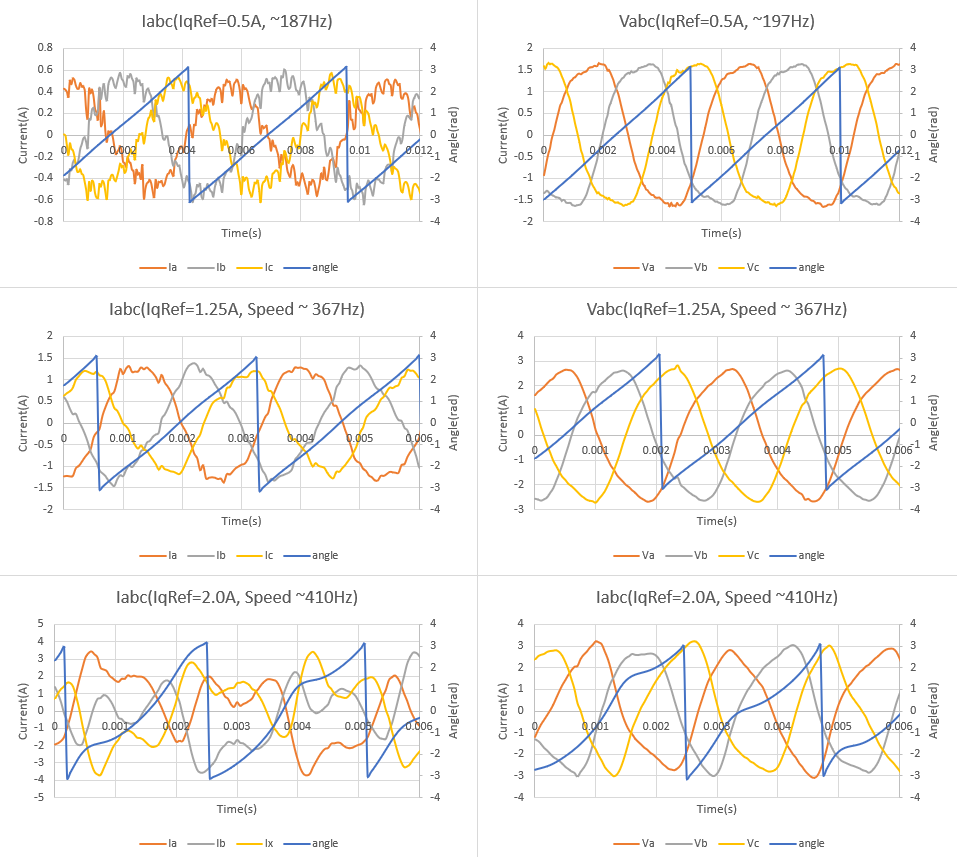
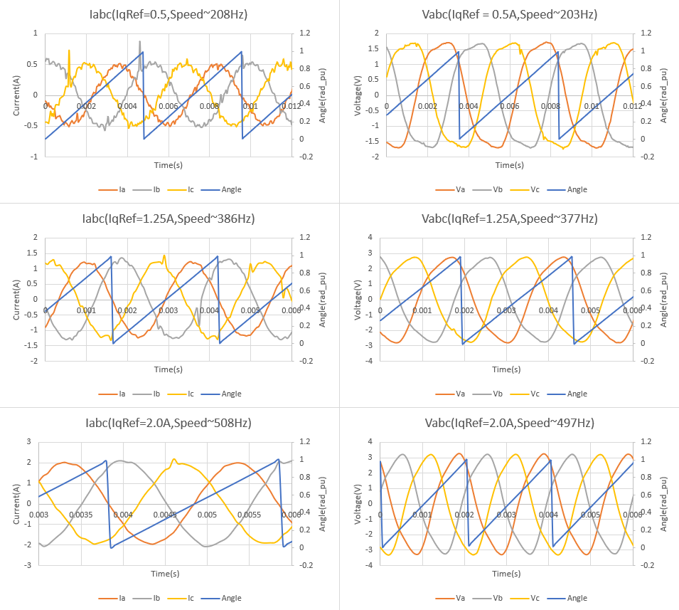
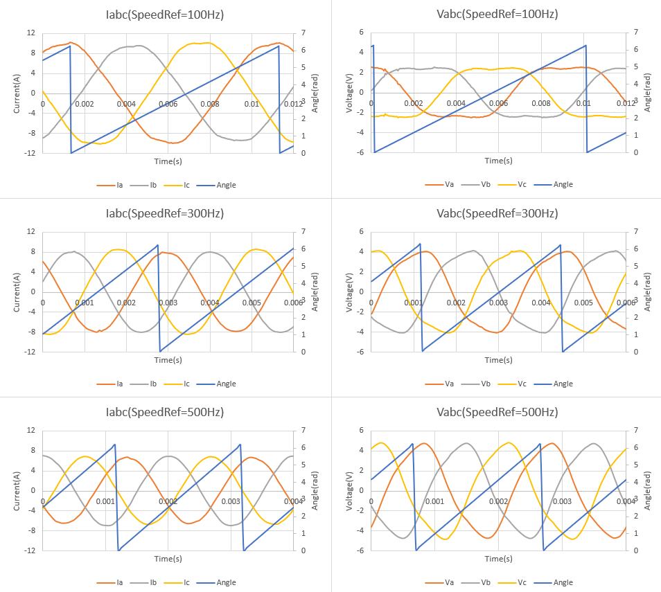
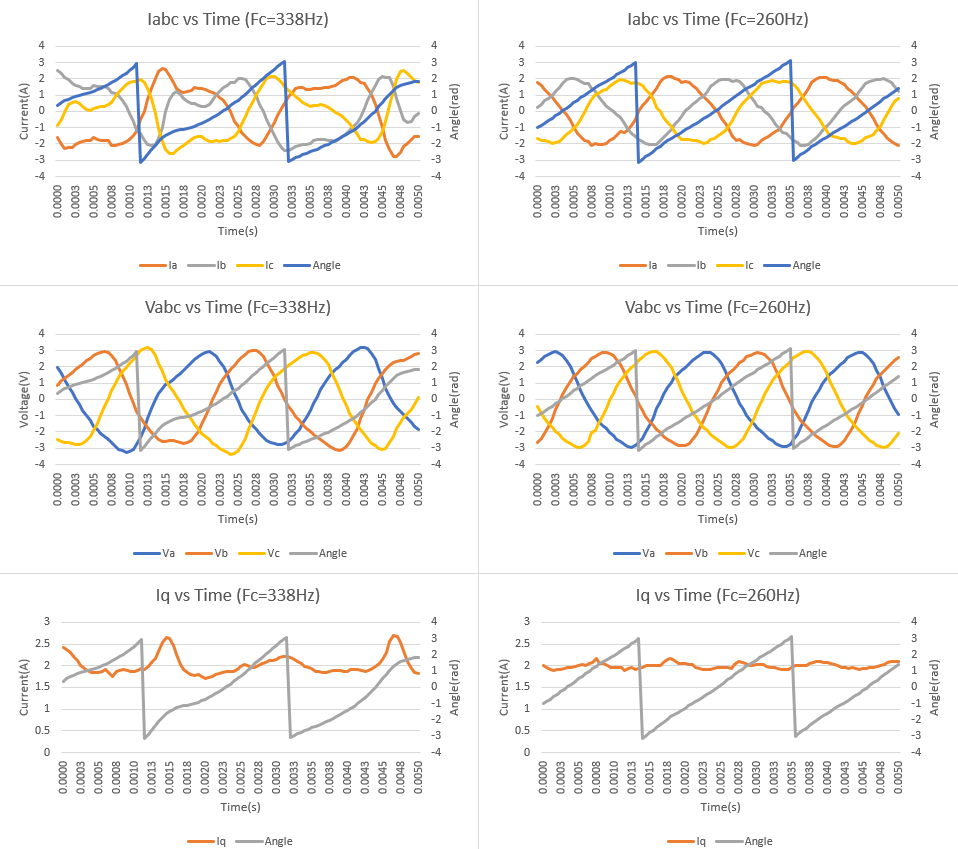
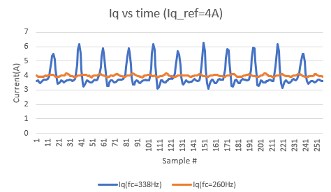
Hello - I am working with the LAUNCHXL-F280049C and BOOSTXL-DRV8320RS to drive a BLDC blower.  I've worked through Labs 5, 6 and 7 and have the drive controlling the blower fairly well.  I am using a 24V power supply and have speed control upto ~ 800 Hz (speed ).  But I noticed when I exceed 400 Hz (speed), I start getting oscillations on the input and reference Iq currents.  I also noticed that the estOutputData.angle_rad starts to get distorted. The primary effect of these oscillations is some motor noise and the speed error gets worst.  Below 400Hz, the speed is locked to ~ +/- 0.1Hz; at 500Hz, the error is ~ +/- 8Hz.  I have adjusted current and speed PI parameters to no avail.  I have also adjusted the ADC sample window and even moved the ADC start point and did not see an improvement.  So i'm looking at the estimator and having questions.  

1.What does the EST_getIab_lp_A function return?  I mean we feed the estimator Iab so does the estimator filter Iab and this function returns the filtered version of Iab?  The function does return values but they don't appear to be the filtered version of Iab.

2. The documentation implies that EST_getIdq_lp_A does the same.  But this function does not appear to work (it returns a constant 0).  Is this function supposed to work?  If so, what value of Iab is it using? Of does it have its own filter?  If so, how are its filter constants set?

3. Is there any documentation that explains the theory behind the estimator?  Something that might help me in trouble shooting this issue?

Thanks!

Brett

  • Both functions are used internally for FAST estimator,  there is a software filter for the current. (sorry I can't give you more details). The high-speed problem is not related to this.

    What rated speed is the motor? You might increase the dc bus voltage to see what happens, to check if the input voltage is enough for high speed running.

  • Mr Luo - thank you for your response.

    I don't think the issue is with the motor speed rating or the input voltage.  

    I basically see the same in labs 5, 6, and 7:  as I get above 400Hz the angle returned from the estimator gets distorted.  If I watch the sampled input currents, they go from sinusoidal to a very distorted signal.  I interpret this to mean the current control is going out of control and causing the reference current to oscillate thus driving what I see on the input current.

    Interestingly, when I run lab 3 I can go up to 800Hz without an issue.  The sampled currents remain sinusoidal.  This is why I don't think the issue is with the motor speed rating or the input voltage.

    I tried varying the PWM frequency and did not see much of a change.

    And as I said, the system works fine (current and speed well controlled) if speed reference is below 400Hz. 

    Any other ideas?

    Brett

  • Could you please post the user.h and motor specification datasheet? The lab03 is a v/f open-loop control without using current sensing signals and the fast estimator. 

  • Mr Luo - attached is the user.h file. The blower datasheet is shown below:

    The blower is delta wound.  And has a 2 pole permanent magnet on the rotor.  I understand the datasheet says 12V and i am driving at 24.  The same problem occurs at 12V.

    As to lab03 being v/f open-loop, i understand.  My point in using lab03 was to show there was no issue with the A/D, PWM, etc in driving and sampling.  

    And as i've said before, we don't have this issue with the LaunchPadXL F28069M/BOOSTXL DRV8301.  The angle never gets distorted even when at 800Hz for speed reference.

    If it would help, i can get you a blower for your testing.

    Thanks again for all of your help.

    Respectfully,

    Brett

    31237.user.h

  • Sorry.  I guess i cant paste a screen shot. Below are the parameters from the blower performance table.

    Terminal Voltage: 12V nominal

    Terminal DC Resistance: 0.294 ohms +/-10% 

    Terminal Inductance (ph-ph): 250uH +/- 18%

    Torque Constant (Calc from Ke): 0.398 Oz-In/Amp +/- 10%

    Back EMF Constant (Peak): 0.295 V/KRPM +/- 10%

    Brett

  • Are you using your own board? Or have you changed something on the TI EVM kit?

    You can try set USER_SPEED_POLE_rps to 500 though the default seems good enough for your motor in the user.h you posted.

  • Brett Nourrcier said:
    But I noticed when I exceed 400 Hz (speed), I start getting oscillations on the input and reference Iq currents.  I also noticed that the estOutputData.angle_rad starts to get distorted.

    Hi Brett,

    You can verify confirm delta stator inductance by running the blower motor with another, scope the phases. I have reservations of SDK in lab5 getting inductance value correct for delta windings. My custom delta motor gave the SDK fits to confirm stable inductance with DRV8320RS at any speed up to 60Hz. There can be Thirsten harmonics in the stator that do not occur in WYE type windings that may effect 3rd AC harmonic according to some text. My view Delta by design is in some ways a form of field weakening since the WYE wire resistance drops by nearly 2/3 and rotor speeds up as a result, fractional HP results. The delta magnetic field is less intense but the Weber/sec increase in the stator windings result of higher current.

    Seemingly why when I tested field weakening no rotor speed up ever occurred, several times only the current doubled, bus voltage drooped.

    Have you tested field weakening, if so what was the result?

  • Mr Luo - i am using the BOOSTXLDRV8320RS as the inverter and the LAUNCHXL-F280049C MCU.

    I have also put this on a custom board that we designed and see the same problem.  That is why i went back to the TI dev boards.  Both have the same problem which is leading me to believe this has something to do with the estimator.  

    NOTE - i can take this same blower and put it on the BOOSTXL DRV8301 inverter and the LAUNCHXL-F28069M MCU and don' have this problem.  I've also run it on the F28027F without issue.

    Brett

  • Hi GI,

    I cant get above 400Hz so trying field weakening is pointless.  I have used field weakening on the MotorWare dev boards without issue.  They also did not have issues with delta wound motors.

    For this one, i think lab5 is ok for measuring motor resistance and inductance. I say this because the values are similar to what i get when using the MotorWare boards. 

    Brett

  • I don't think the estimator has any issue to run the motor with 400Hz, even 800Hz (maybe need field weakening for 600+Hz if the dc bus voltage is 12V) per the parameters in user.h you posted. The same algorithm of the estimators is used in F28004x and F2806x/F2802x, just migrate the Per-Unit to floating-point format on F28004x. We have tested both blower and drone motors on boostxl-drv8320 with spinning run up to 1000Hz. 

    You might change the voltage sampling circuit to improve the resolution of voltage sensing signals as the BOOSTXL-DRV8301, that should be useful to the low BEMF constant motor.

    Lab04 only verify the current sensing by using closed current loop. Both lab03 and lab04 don't use the voltage sensing signals for motor control, you have to check if voltage sensing is good by datalog or PWMDAC, and verify the voltage sensing by using lab05 to check if the identified motor parameters are correct.

    Please post some phase current waveform captured by the scope and the pictures of the distorted angle you mentioned above if possible. We'd like to close this thread, please create a new thread if you have further questions, or keep the discussion in another thread you posted.

  • Mr Luo - thank you.  Maybe this will help? 

    I setup Lab IS06 to capture voltage and current samples.  Basically, each time the main ISR is called i capture angle, Valpha, Vbeta, Ialpha, Ibeta, Id, and Iq.  The capture is started on a manual trigger i set once the blower is stable at speed.  I capture 256 samples using 20kHz sample rate.  Input voltage is 24V and at no time is the power supply current limited.

    The following shows Valpha, beta when Iq_ref = 0.25A, 1.0A, and 2.0A::

    The next charts show angle when Iq_ref =  0.25A, 1.0A, and 2.0A:

    Next chart shows I alpha, beta for Iq_ref = 0.25A, 1.0A, and 2.0A:

    And finally, the following charts show Idq when Iq_ref = 0.25A, 1.0A, and 2.0A:

    Anyway, something is going on when i transition to 2A and i cant figure out how to resolve.  I don' see this in the F28069M/DRV8301 dev board using MotorWare.  I am using the same Ki and Kp in both setups...

    From your comments above, when you say change the voltage sampling circuit are you saying change the hardware?  I see the same issue on our internal design where we setup for a 24V max input (4.99K, 40.2K voltage divider).

    Thanks!

    Brett

  • Sorry.  The charts did not transfer?  

    Let me try again.  Attached is the excel file with the data and charts.  The summary page has the charts.

    ThxVoltage and Current and Angle Data for various Iq_ref values.xlsxanks!

    Brett

  • You should use different Kp and Ki on the project of F28004x and F2806x, because the F28004x uses the SI format in the project, and F2806x uses the PU format. 

    You might try the lab07 to see if there is the same issue without changing the default Kp and Ki for current controllers.

  • Mr Luo - thank you for responding but unfortunately this did not help. 

    Yes i understand the format is different (IQ vs floating point).  And yes i understand that one is scaled and the other is not.  That is why i am focusing on the current controller and ignoring the speed controller for now.  Here is what i have.  Please correct me if i am wrong:

    1. I get similar values for Ls and Rs (and flux) when i run MotorWare (Lab 2c) or MotorControl (Lab 5).  Does this tell us something?

    2. I am running the PWM frequency at 20,000Hz for both MotorWare and MotorControl.  Both programs run the current controllers on each call to the  ISR.

    3. The Ki value used for both programs is the same:  Ki = (Rs/Ls)*Ti where Ti = 1/20,000.

    4. The default Kp values are different between the 2 programs.  To make equivalent, i use the following:

    4.a. Kp (MotorWare) = (0.25*Ls/Ti)*(USER_IQ_FULL_SCALE_CURRENT_A/USER_IQ_FULL_SCALE_VOLTAGE).  This is the default calculation for MotorWare.

    4.b. Kp (MotorControl) = 0.25*Ls/Ti.  This is not the default calculation but this make the 2 Kp values equivalent.  Correct?

    5. As i said above, both programs run fine until speed gets to 400Hz.  Up to 400Hz, there is no difference between the 2 programs when comparing the I_ab and I_dq current waveforms.  But as the speed exceeds 400Hz, MotorWare (Lab 5a) runs fine in that the angle returned by the estimator is linear and the I_ab and I_dq currents seem to respond correctly. But with the MotorControl program (Lab 6), the angle distorts and the current's I_ab and I_dq seem to go out of "control".

    6. But you don't see these issues?  

    7. Is the angle determined from the 3 phase voltages?  Could there be something in how MotorControl is sampling or filtering or? that is causing this problem? 

    8. The fact that i see the problem on different F280049C boards seems to say this is not a flaw in my specific hardware. 

    9. I understand lab 3 is not using the estimator.  But the fact that i can run the blower past 400Hz should tell us something?  Doesnt it say the sampling circuits for voltage and current are working correctly? 

    Brett

  • Hi Brett,

    Brett Nourrcier said:
    I see the same issue on our internal design where we setup for a 24V max input (4.99K, 40.2K voltage divider).

    I had similar values on my custom DC inverter for use with 6 step FOC, that produces samples closer to LSB contrary to Motorware technical mention need of MSB. Also noted better ADC results in lab5 dividers (102k) reduced to (75k) and samples then produced better even believable inductance values. All analog voltage dividers must be the same resistor values 1%-2% tolerance.

    If you see the line voltage droop on any phase rotor nearing 400Hz that is seemingly an indication of ADC sample value injecting SNR distortion into the equation. Seemingly distortion of the current waveform results in limited rotor speed, hence the need/request to post current captures. The quest to produce a clean 3rd harmonic as I understand, check link below. Best of luck to get that rotor spinning >400Hz soon.

    https://www.youtube.com/watch?v=nh9TD2M2r-o

  • Hi Brett,

    Did you run the lab06 and lab07 with the default gains of the current controller? If you still have issue, please post the user.h you used, so I can find a similar motor to have a test. I have ever tested a low voltage high current drone motor on LaunchPad-F280049C + BoostXL-DRV8320RS, the motor even ran up to the 1500kHz frequency (Electrical) without any issue, so I don't think there is any difference and issue using FAST estimator on F280049C to run the motor with high speed compare to on the F2802xF/F2806xF.

  • Mr Luo - thank you for your response.  

    1. Yes i have run Lab06(IS06) and Lab07(IS07) with the default gains and still got the same issue.

    2. The graphs below show Iabc and Vabc obtained from Lab06 (IS06).  I sampled once per ISR call and collected 256 samples.  I collected for IqRef = 0.5A, 1.25A, and 2.0A.  

    3. This next chart shows the same graphs obtained from Lab5a using the 69M development board.

    4. The Kp and Ki parameters for the current controllers are calculated as above for both the 49C and the 69M dev boards.

    5. Clearly something is going wrong in the 49C when IqRef= 2.0A.

    6. I ran Lab03(IS03) as a check to verify the analog input circuits were working correctly.  The chart below shows Iabc and Vabc for 3 values (100Hz, 300Hz, and 500Hz) of SpeedRef:

    7. These appear correct...???

    8. Attached is the user.h file (49C) and the user_1j.h file (69M).

    9. If you would like one of these blowers for testing, please send me an email with ship to information and i will have it shipped.

    Thanks again for all of your help.

    Brett5428.user.h4861.user_j1.h

  • Hi Brett,

    Curious is there an RS impedance or internal charge cap difference between the two ADC's being tested? The 2.0A wave forms (49c) look as if for some reason oscillation distortion is being injected into the current channels. So the angle looses integrity as each sector falls behind or moves slightly ahead as the rotation angle oscillates near the induced harmonic. 

    Of particular interest the grey wave (49c/2.0A) is following the rotation angle rise/fall slopes almost implicitly. The 69M analog inputs appear to have refined analog filters that removes the dreaded current oscillations near 410Hz. It may simply be the PGA input signals of low pass filters on drv8320rs are to blame under certain conditions, oversampling may improve sample values in that area.

  • Hey GI - for the 49C, the filters (V & I) are before the PGA/ADC.  For the 69M, the filters are between the PGA and the ADC.  The filter values for the current signals are the same between the 2 boards; the filter values for the voltage signals are different (34.8k/4.99k for the 69M, 82.0k/4.99k for the 49C).  This may account for some noise but i dont think that is what i am seeing.

    I did increase the PWM frequency from 20kHz to 40kHz but did not see an improvement.

    Brett

  • Mr Luo - i worked more on this problem today.

    1. Adjusting the sample window (from 15 to 512) did not seem to make a difference.

    2. Adjusting the PWM frequency does seem to help.  I can run the blower with pwm frequency set from 10kHz to 40kHz.  Interestingly, the system seems more stable at 10kHz.  Any thoughts on why the lower pwm frequency helps?

    3. The ISR cycle time (time spent in the ISR) is ~ 21.5us with the data logger enabled and about 20.5us when the data logger is not enabled.

    4. The background tasks take about 8.5us to execute.

    5. I disabled the MATH_SAT functions in the PI controllers to see if they may be causing the problem.  They were not.  Problem persisted.

    6. I removed the angle delay compensation; no help.

    7. I am not sure what else to look at.  Hopefully these clues help.   

    Brett

  • Hi Brett,

    Brett Nourrcier said:
    I did increase the PWM frequency from 20kHz to 40kHz but did not see an improvement.

    Yet you did not try to do ADC oversampling try to quiet the current sub-harmonic in the sample window, TRM13.5 SOC Principle of Operation. Perhaps try to make the sample window shorter if oversampling is not possible may avoid parasitic oscillations. BTW sub-harmonic current oscillation is a known issue in TPS40210 SEPIC power stage, recently read about came to mind for this post.

    The motors stator may be the cause of induced current harmonic and the DRV8320RS lowpass input filter simply passes a sub-harmonic into ADC. You can also enable the 49c PGA output filters (300pF) already placed on the launch pad and adjust the resistor value via (Rfilter) TRM 14.1 to 14.4.

  • Hey GI - thank you for the suggestion.  I've never really looked at site 2 before.  Anyway, i did as you suggested and setup the PGA filter.  This definitely did not completely solve the problem in that i still see distortion on the angle and on the Iabc input currents.  But, with that said, the system does seem to be more stable and seems to make sense when i make changes.  For example, before i could not really see much difference when i raised or lowered the PWM frequency - which really didnt make any sense.  Now, i see a marked improvement as i increase frequency - which makes sense.  The Kp and Ki terms also seem to have more of an effect as i adjust them.  

    This still feels like an estimator issue.

    Thank again for your suggestion.

    Brett

  • HI Brett,

    Brett Nourrcier said:
    This definitely did not completely solve the problem in that i still see distortion on the angle and on the Iabc input currents.

    Did you remove 0R's on site 2 external filters? I prefer site 2 as the launch pad LED's can be easily seen otherwise directly under booster pack. There was an issue with HAL_setupGate had to changed by edit as I recall.  

    BoosterPack site 2 has the associated output filter signals routed. Each output filter signal has two components: a 0 Ω series resistor and a decoupling capacitor.

    If the PGA output filters are used, remove the 0Ω series resistor to isolate it from the BoosterPack connector, and place an appropriate filter capacitor. By default, a 330 pF capacitor is populated.

    An isolated ground plane for the PGAs has been created to help limit outside noise coupling onto the PGA signals. By default, this ground plane is shorted to the ground plane of the PCB through a resistor. If isolation between PGAx_GND and the PCB ground is needed the resistor can be removed.

  • Hey GI - yes i removed the three (3) 0ohm resistors (R19, R22, R25) from the PGA_OF trace.  I left the ground plane as is.  And i changed to ADC inputs to match the PGA_OF inputs (C9->C8, A15-A8, B9->B8).  There was also an issue with PIN 32 in HAL_setupGPIOs that i fixed.  I didnt see anything wrong with the HAL_setupGate routine.

    Brett

  • Brett Nourrcier said:
    HAL_setupGate routine

    Yea it defaults to SPI-A[0] and you have to SPI-B[1] on Site 2. It was difficult to get Site 2 working at first, escapes me now but it may been GPIO PIN-32 user LED was linked to pin 31 in my note. And GPIO 30 is mainISR() decimation interrupt pulse out. I sync scope to 50µs PWM pulse count number of ticks set in the user.h was/is not being over run in 50µs period.

    You can also run SDK labs on your custom PCB connected 49c launch pad via short jumpers. It was really simple to make a few SW changes thus remove/REM SPIn control in hal.c and each lab. Thought was to connect your original F69 inverter to 49c launch pad and/or bypass PGA's filters. 

    Check SPI-B control pins in/out are set for asynchronous mode, GPIO default to synchronous

       GPIO_setQualificationMode(31, GPIO_QUAL_ASYNC);

  • Mr Luo - i hope this finds you well.

    1. I never saw a response to the above.

    2. I thought about your comment on the voltage filter and looked to make sure the user parameter (USER_VOLTAGE_FILTER_POLE_Hz) was set correctly.  The calculated cutoff frequency is 344Hz; the user parameter is set at 338Hz.  

    3. Changing the parameter to 344Hz did not remove the distortion.

    4. BUT, after some iterations on USER_VOLTAGE_FILTER_POLE_Hz, I found that the distortion gets less as the parameter is reduced.  260Hz seems optimal for this blower.  

    5. The only downside i have seen is the reported speed from EST_getFM_lp_Hz seems to be affected if the USER_VOLTAGE_FILTER_POLE_Hz is set too low.  

    Can you tell me how this filter pole is used in the estimator?  I understand the  hardware filter is used to filter out the PWM signals.  But i dont understand what the estimator is doing with the parameter.  Is it doing a software filter and that is why a change in the parameter seems to have an effect on the estimator? 

    Thanks for you help!

    Brett

  • Hi Brett,

    In my experience, I think the root cause of your problem is the current gain.

    Generally, the current bandwidth (BWc_rps) should be in the range of 2pi*(1/Ts)*(1/30)  to 2pi*(1/Ts)*(1/10) for the best dynamic performance.  The current bandwidth in MotorWare was about 2pi*(1/Ts)*(1/25). However, the current bandwidth in MC_SDK uses a fixed value  2pi*100. This value is too low for high speed applications. 

    You can modify the default bandwidth in user.c as shown below. As you can see, the current bandwidth should be calculated based on the current control frequency.  This code was meant to be executed only if it is a bypass motor identification condition.

    //------------------------------------------------------------------------------------------------------------------------------------

    if((USER_BYPASS_MOTOR_ID == 1) || (pUserParams->flag_bypassMotorId == true))
    {
        pUserParams->BWc_rps = MATH_TWO_PI * (float_t)1.0 / USER_CTRL_PERIOD_sec * (float_t)0.04;
        pUserParams->BWdelta = (float_t)20.0;
        pUserParams->Kctrl_Wb_p_kgm2 = (float_t)1.5 * pUserParams->motor_numPolePairs * pUserParams->motor_ratedFlux_Wb /  (float_t)0.000004802;
    }
    else
    {

       pUserParams->BWc_rps = MATH_TWO_PI * (float_t)100.0;
       pUserParams->BWdelta = (float_t)10.0;
       pUserParams->Kctrl_Wb_p_kgm2 = (float_t)1.5 * pUserParams->motor_numPolePairs * (float_t)(0.001) / (float_t)(0.000001);
    }

    //-------------------------------------------------------------------------------------------------------------------------------------

    Please refer to the attached file I've been using. You can replace user.c file in the "libraries\observers\est\source" folder with mine.

    8831.user.c
    //#############################################################################
    //
    // FILE:   user.c
    //
    // TITLE:  C28x InstaSPIN function for setting initialization data for the
    //         CTRL, HAL, and EST modules (floating point)
    //
    //#############################################################################
    // $TI Release: MotorControl SDK v3.00.00.00 $
    // $Release Date: Fri Mar 27 13:04:40 CDT 2020 $
    // $Copyright:
    // Copyright (C) 2017-2018 Texas Instruments Incorporated - http://www.ti.com/
    //
    // Redistribution and use in source and binary forms, with or without
    // modification, are permitted provided that the following conditions
    // are met:
    //
    //   Redistributions of source code must retain the above copyright
    //   notice, this list of conditions and the following disclaimer.
    //
    //   Redistributions in binary form must reproduce the above copyright
    //   notice, this list of conditions and the following disclaimer in the
    //   documentation and/or other materials provided with the
    //   distribution.
    //
    //   Neither the name of Texas Instruments Incorporated nor the names of
    //   its contributors may be used to endorse or promote products derived
    //   from this software without specific prior written permission.
    //
    // THIS SOFTWARE IS PROVIDED BY THE COPYRIGHT HOLDERS AND CONTRIBUTORS
    // "AS IS" AND ANY EXPRESS OR IMPLIED WARRANTIES, INCLUDING, BUT NOT
    // LIMITED TO, THE IMPLIED WARRANTIES OF MERCHANTABILITY AND FITNESS FOR
    // A PARTICULAR PURPOSE ARE DISCLAIMED. IN NO EVENT SHALL THE COPYRIGHT
    // OWNER OR CONTRIBUTORS BE LIABLE FOR ANY DIRECT, INDIRECT, INCIDENTAL,
    // SPECIAL, EXEMPLARY, OR CONSEQUENTIAL DAMAGES (INCLUDING, BUT NOT
    // LIMITED TO, PROCUREMENT OF SUBSTITUTE GOODS OR SERVICES; LOSS OF USE,
    // DATA, OR PROFITS; OR BUSINESS INTERRUPTION) HOWEVER CAUSED AND ON ANY
    // THEORY OF LIABILITY, WHETHER IN CONTRACT, STRICT LIABILITY, OR TORT
    // (INCLUDING NEGLIGENCE OR OTHERWISE) ARISING IN ANY WAY OUT OF THE USE
    // OF THIS SOFTWARE, EVEN IF ADVISED OF THE POSSIBILITY OF SUCH DAMAGE.
    // $
    //#############################################################################
    
    #include "user.h"
    
    #ifdef __TMS320C28XX_CLA__
    #pragma CODE_SECTION(USER_setParams,"Cla1Prog2");
    #endif
    
    #ifdef _F28002x_
    #pragma CODE_SECTION(USER_setParams, "user_code");
    #endif
    
    //*****************************************************************************
    //
    // USER_setParams
    //
    //*****************************************************************************
    void USER_setParams(USER_Params *pUserParams)
    {
        pUserParams->dcBus_nominal_V = USER_NOMINAL_DC_BUS_VOLTAGE_V;
    
        pUserParams->numIsrTicksPerCtrlTick = 1;
        pUserParams->numIsrTicksPerEstTick = 1;
        pUserParams->numIsrTicksPerTrajTick = 1;
    
        pUserParams->numCtrlTicksPerCurrentTick = USER_NUM_ISR_TICKS_PER_CURRENT_TICK;
        pUserParams->numCtrlTicksPerSpeedTick = USER_NUM_ISR_TICKS_PER_SPEED_TICK;
    
        pUserParams->numCurrentSensors = USER_NUM_CURRENT_SENSORS;
        pUserParams->numVoltageSensors = USER_NUM_VOLTAGE_SENSORS;
    
        pUserParams->systemFreq_MHz = USER_SYSTEM_FREQ_MHz;
    
        pUserParams->voltage_sf = USER_VOLTAGE_SF;
    
        pUserParams->current_sf = USER_CURRENT_SF;
    
        pUserParams->dcBusPole_rps = USER_DCBUS_POLE_rps;
    
        pUserParams->offsetPole_rps = USER_OFFSET_POLE_rps;
    
        pUserParams->speedPole_rps = USER_SPEED_POLE_rps;
    
        pUserParams->voltageFilterPole_rps = USER_VOLTAGE_FILTER_POLE_rps;
    
        pUserParams->RoverL_excFreq_Hz = USER_R_OVER_L_EXC_FREQ_Hz;
    
        pUserParams->maxVsMag_pu = USER_MAX_VS_MAG_PU;
    
        pUserParams->motor_type = USER_MOTOR_TYPE;
    
        pUserParams->motor_numPolePairs = USER_MOTOR_NUM_POLE_PAIRS;
        pUserParams->motor_numEncSlots = USER_MOTOR_NUM_ENC_SLOTS;
    
        pUserParams->motor_ratedFlux_Wb = USER_MOTOR_RATED_FLUX_VpHz / MATH_TWO_PI;
    
        pUserParams->motor_Rr_d_Ohm = USER_MOTOR_Rr_Ohm;
        pUserParams->motor_Rr_q_Ohm = USER_MOTOR_Rr_Ohm;
    
        pUserParams->motor_Rs_a_Ohm = USER_MOTOR_Rs_Ohm;
        pUserParams->motor_Rs_b_Ohm = USER_MOTOR_Rs_Ohm;
    
        pUserParams->motor_Rs_d_Ohm = USER_MOTOR_Rs_Ohm;
        pUserParams->motor_Rs_q_Ohm = USER_MOTOR_Rs_Ohm;
    
        pUserParams->motor_Ls_d_H = USER_MOTOR_Ls_d_H;
        pUserParams->motor_Ls_q_H = USER_MOTOR_Ls_q_H;
    
        pUserParams->maxCurrent_A = USER_MOTOR_MAX_CURRENT_A;
    
        pUserParams->IdRated_A = USER_MOTOR_MAGNETIZING_CURRENT_A;
    
        pUserParams->Vd_sf = USER_VD_SF;
        pUserParams->maxVsMag_V = USER_NOMINAL_DC_BUS_VOLTAGE_V;
    
        /*LDRA_INSPECTED 139 S MR12 14.3 ""Its a compile time flag providing user a
           choice to use or bypass motor identification; so OK"*/
        if((USER_BYPASS_MOTOR_ID == 1) || (pUserParams->flag_bypassMotorId == true))
        {
            pUserParams->BWc_rps = MATH_TWO_PI * (float_t)1.0 / USER_CTRL_PERIOD_sec * (float_t)0.04;
            pUserParams->BWdelta = (float_t)20.0;
            pUserParams->Kctrl_Wb_p_kgm2 = (float_t)1.5 *
                                           pUserParams->motor_numPolePairs *
                                           pUserParams->motor_ratedFlux_Wb /
                                           (float_t)0.000004802;
        }
        else
        {
    
            pUserParams->BWc_rps = MATH_TWO_PI * (float_t)100.0;
            pUserParams->BWdelta = (float_t)10.0;
            pUserParams->Kctrl_Wb_p_kgm2 = (float_t)1.5 *
                                           pUserParams->motor_numPolePairs *
                                           (float_t)(0.001) /
                                           (float_t)(0.000001);
        }
    
        pUserParams->angleDelayed_sf_sec = (float32_t)1.5 * USER_CTRL_PERIOD_sec; //0.5->1.5
    
        pUserParams->fluxExcFreq_Hz = USER_MOTOR_FLUX_EXC_FREQ_Hz;
    
        pUserParams->ctrlWaitTime[CTRL_STATE_ERROR] = 0;
        pUserParams->ctrlWaitTime[CTRL_STATE_IDLE] = 0;
        pUserParams->ctrlWaitTime[CTRL_STATE_ONLINE] = 0;
    
        pUserParams->estWaitTime[EST_STATE_ERROR] = 0;
        pUserParams->estWaitTime[EST_STATE_IDLE] = 0;
        pUserParams->estWaitTime[EST_STATE_ROVERL] =
            (int32_t)(5.0 * USER_EST_FREQ_Hz);
        pUserParams->estWaitTime[EST_STATE_RS] = 0;
        pUserParams->estWaitTime[EST_STATE_RAMPUP] =
            (int32_t)((USER_MOTOR_FLUX_EXC_FREQ_Hz / USER_MAX_ACCEL_Hzps +
                             (float32_t)1.0) * USER_EST_FREQ_Hz);
        pUserParams->estWaitTime[EST_STATE_CONSTSPEED] =
            (int32_t)(1.0 * USER_EST_FREQ_Hz);
        pUserParams->estWaitTime[EST_STATE_IDRATED] =
            (int32_t)(20.0 * USER_EST_FREQ_Hz);
        pUserParams->estWaitTime[EST_STATE_RATEDFLUX_OL] =
            (int32_t)(1.0 * USER_EST_FREQ_Hz);
        pUserParams->estWaitTime[EST_STATE_RATEDFLUX] = 0;
        pUserParams->estWaitTime[EST_STATE_RAMPDOWN] =
            (int32_t)(0.0 * USER_EST_FREQ_Hz);
        pUserParams->estWaitTime[EST_STATE_LOCKROTOR] = 0;
        pUserParams->estWaitTime[EST_STATE_LS] = 0;
        pUserParams->estWaitTime[EST_STATE_RR] =
            (int32_t)(5.0 * USER_EST_FREQ_Hz);
        pUserParams->estWaitTime[EST_STATE_MOTORIDENTIFIED] = 0;
        pUserParams->estWaitTime[EST_STATE_ONLINE] = 0;
    
        pUserParams->FluxWaitTime[EST_FLUX_STATE_ERROR] = 0;
        pUserParams->FluxWaitTime[EST_FLUX_STATE_IDLE] = 0;
        pUserParams->FluxWaitTime[EST_FLUX_STATE_CL1] =
            (int32_t)(10.0 * USER_EST_FREQ_Hz);
        pUserParams->FluxWaitTime[EST_FLUX_STATE_CL2] =
            (int32_t)(0.2 * USER_EST_FREQ_Hz);
        pUserParams->FluxWaitTime[EST_FLUX_STATE_FINE] =
            (int32_t)(20.0 * USER_EST_FREQ_Hz);
        pUserParams->FluxWaitTime[EST_FLUX_STATE_DONE] = 0;
    
        pUserParams->LsWaitTime[EST_LS_STATE_ERROR] = 0;
        pUserParams->LsWaitTime[EST_LS_STATE_IDLE] = 0;
        pUserParams->LsWaitTime[EST_LS_STATE_RAMPUP] =
            (int32_t)(10.0 * USER_EST_FREQ_Hz);
        pUserParams->LsWaitTime[EST_LS_STATE_COARSE] =
            (int32_t)(30.0 * USER_EST_FREQ_Hz);
        pUserParams->LsWaitTime[EST_LS_STATE_FINE] =
            (int32_t)(30.0 * USER_EST_FREQ_Hz);
        pUserParams->LsWaitTime[EST_LS_STATE_DONE] = 0;
    
        pUserParams->RrWaitTime[EST_RR_STATE_ERROR] = 0;
        pUserParams->RrWaitTime[EST_RR_STATE_IDLE] = 0;
        pUserParams->RrWaitTime[EST_RR_STATE_RAMPUP] =
            (int32_t)(1.0 * USER_EST_FREQ_Hz);
        pUserParams->RrWaitTime[EST_RR_STATE_COARSE] =
            (int32_t)(10.0 * USER_EST_FREQ_Hz);
        pUserParams->RrWaitTime[EST_RR_STATE_FINE] =
            (int32_t)(30.0 * USER_EST_FREQ_Hz);
        pUserParams->RrWaitTime[EST_RR_STATE_DONE] = 0;
    
        pUserParams->RsWaitTime[EST_RS_STATE_ERROR] = 0;
        pUserParams->RsWaitTime[EST_RS_STATE_IDLE] = 0;
        pUserParams->RsWaitTime[EST_RS_STATE_RAMPUP] =
            (int32_t)(1.0 * USER_EST_FREQ_Hz);
        pUserParams->RsWaitTime[EST_RS_STATE_COARSE] =
            (int32_t)(2.0 * USER_EST_FREQ_Hz);
        pUserParams->RsWaitTime[EST_RS_STATE_FINE] =
            (int32_t)(3.0 * USER_EST_FREQ_Hz);
        pUserParams->RsWaitTime[EST_RS_STATE_DONE] = 0;
    
        pUserParams->trajWaitTime[EST_TRAJ_STATE_ERROR] = 0;
        pUserParams->trajWaitTime[EST_TRAJ_STATE_IDLE] = 0;
        pUserParams->trajWaitTime[EST_TRAJ_STATE_EST] = 0;
        pUserParams->trajWaitTime[EST_TRAJ_STATE_ONLINE] = 0;
    
        pUserParams->estFreq_Hz = USER_EST_FREQ_Hz;
        pUserParams->ctrlFreq_Hz = USER_CTRL_FREQ_Hz;
        pUserParams->trajFreq_Hz = USER_TRAJ_FREQ_Hz;
    
        pUserParams->pwmPeriod_usec = USER_PWM_PERIOD_usec;
        pUserParams->ctrlPeriod_sec = USER_CTRL_PERIOD_sec;
    
        pUserParams->maxAccel_Hzps = USER_MAX_ACCEL_Hzps;
    
        pUserParams->maxCurrent_resEst_A = USER_MOTOR_RES_EST_CURRENT_A;
        pUserParams->maxCurrent_indEst_A = USER_MOTOR_IND_EST_CURRENT_A;
    
        pUserParams->maxCurrentDelta_A = USER_MAX_CURRENT_DELTA_A;
        pUserParams->maxCurrentDelta_pw_A = USER_MAX_CURRENT_DELTA_PW_A;
    
        pUserParams->IdRated_delta_A = USER_IDRATED_DELTA_A;
    
        pUserParams->forceAngleFreq_Hz = USER_FORCE_ANGLE_FREQ_Hz;
    
        pUserParams->indEst_speedMaxFraction = USER_SPEEDMAX_FRACTION_FOR_L_IDENT;
    
        pUserParams->IdRatedFraction_indEst = USER_IDRATED_FRACTION_FOR_L_IDENT;
    
        pUserParams->pwGain = USER_PW_GAIN;
    
        pUserParams->Kp_min_VpA = (float32_t)0.001;
        pUserParams->Kp_max_VpA = (float32_t)1000.0;
    
        pUserParams->RoverL_Kp_sf = USER_R_OVER_L_KP_SF;
        pUserParams->RoverL_min_rps = MATH_TWO_PI * (float32_t)5.0;
        pUserParams->RoverL_max_rps = MATH_TWO_PI * (float32_t)5000.0;
    
        pUserParams->oneOverDcBus_min_invV = (float32_t)1.0 / (float32_t)400.0;
        pUserParams->oneOverDcBus_max_invV = (float32_t)1.0 / (float32_t)10.0;
    
        pUserParams->Ls_d_H = (float32_t)1.0e-6;
        pUserParams->Ls_q_H = (float32_t)1.0e-6;
        pUserParams->Ls_coarseDelta_H = (float32_t)0.0000001;
        pUserParams->Ls_fineDelta_H = (float32_t)0.00000001;
        pUserParams->Ls_min_H = (float32_t)0.000001;
        pUserParams->Ls_max_H = (float32_t)100.0;
    
        pUserParams->Rr_Ohm = (float32_t)0.0;
        pUserParams->Rr_coarseDelta_Ohm = (float32_t)0.0001;
        pUserParams->Rr_fineDelta_Ohm = (float32_t)0.00001;
        pUserParams->Rr_min_Ohm = (float32_t)0.0;
        pUserParams->Rr_max_Ohm = (float32_t)1000.0;
    
        pUserParams->Rs_Ohm = (float32_t)0.0;
        pUserParams->Rs_coarseDelta_Ohm = (float32_t)0.01;
        pUserParams->Rs_fineDelta_Ohm = (float32_t)0.00001;
        pUserParams->Rs_min_Ohm = (float32_t)0.001;
        pUserParams->Rs_max_Ohm = (float32_t)1000.0;
    
        pUserParams->RsOnLine_DeltaInc_Ohm = (float32_t)0.00001;
        pUserParams->RsOnLine_DeltaDec_Ohm = (float32_t)0.00001;
        pUserParams->RsOnLine_min_Ohm = (float32_t)0.001;
        pUserParams->RsOnLine_max_Ohm = (float32_t)1000.0;
    
        pUserParams->RsOnLine_angleDelta_rad = (float32_t)0.00001;
        pUserParams->RsOnLine_pole_rps = MATH_TWO_PI * (float32_t)0.2;
    
        pUserParams->flag_bypassMotorId = USER_BYPASS_MOTOR_ID;
    
        return;
    } // end of USER_setParams() function
    
    
    // end of file
    

    -Steve

  • Steve - thank you.  I have been using the Motorware BW calculation but i went ahead and loaded your file.  I noticed  you changed the angleDelayed_sf_sec from 0.5 to 1.5.

    Anyway, I got the same results with the new file. 

    The graphs below show Iabc, Vabc, and Iq for 2 different values of USER_VOLTAGE_FILTER_POLE_Hz: 338Hz which is default and 260Hz.  These runs were done using lab is06 with Iq_ref = 2.0A, pwm frequency = 20kHz.  The only difference between these 2 runs is the USER_VOLTAGE_FILTER_POLE_Hz value.

    If i increase Iq_ref, the Iq for the default setting gets worse when compared to the 266Hz setting.  The graph below shows both when Iq_ref=4A.

    I think this is saying something but i am not sure how the estimator is using this parameter.  

    Can you share how the estimator is using this parameter?

    Any thoughts on the downside of modifying this parameter?

    Thanks!

    Brett

  • Brett,

    The FAST estimator is based on BEMF. Most of BEMF based sensorless observer including FAST need motor input phase voltage, current and motor electrical parameters(R, L,..) to estimate BEMF. 
    Unlike other sensorless algorithms, the FAST works with phase voltage feedback to get the exact actual motor input phase voltage. So, voltage filter parameter in user.h should be exactly same with you hardware voltage filter cutoff frequency. This voltage filter parameter directly effects the calculation of input voltage from filtered voltage. Sorry but it's hard to reveal more information about FAST estimator.  

    I understand you are suspicious new floating-point FAST version of F28004x because there was no issue at fixed-point version with your same motor. However. obviously, the present issue you faced has nothing to the with FAST itself. A lot of InstaSPIN-FOC issues encountered while supporting F28004x  over the years turned out as user HW and SW issue including MC_SDK. The floating-point FAST version showed the better performance than before in many cases. Also, even over 800Hz, there was no problem. 

    Because the FAST estimator is also a closed loop system, it's very difficult to find root cause of this issue from the test results you posted. As you see the test result with changing voltage filter parameter, you might see similar result from changing other parameters like L, R and current. My recommendation is you have to find the root cause after using exact all motor and system parameters in user.h.    

    Here is my questions.

    Q1) Are you using motor parameters from lab_is05_motor_id or motor data sheet?  It seems the motor parameters in user.h are very different from the actual motor parameters you posted. 

    Q2)  Could you show me the current PI gains in CCS watch window? 

    If possible, let me also try to test a high speed motor with LAUNCHXL_F280049C +  BOOSTXL_DRV8320RS. It may take some time because I don't have high speed motor right now.

    Regards,

    Steve 

  • Hey Steve - thank you for your response.

    1. I am using motor parameters obtained from lab_is05.  These motor parameters closely match the same parameters obtained from the MotorWare labs.  I have never been able to exactly match the datasheet R&L values to what TI returns.  The fact that the motor runs well under MotorWare made me believe that the parameters were/are what the TI algorithm needs.  The motor is delta wound.  The datasheet R & L values are phase to phase values with the 3rd phase floating.

    2. Screen shot below.  Fpwm=20kHz. 1 pole pair. Rs = 0.178 ohm; Ls = 0.000148 H. Iq_ref = 1A.

    3. I can send you one of these blowers.  I would really like to do so because i think this would allow you to see exactly what we are seeing.

    Some comments on what you posted:

    1. I have adjusted Ki and Kp (using the TI tuning guide and blindly) without affecting this issue. 

    2. With that said, i tried to set R & L to the datasheet values.  The motor would slowly cog from phase to phase but never ran properly.  I can play with these values but i am not sure this will get us closer.

    3. Why do you dismiss the filter pole so quickly?  Not being an estimator expert (obviously), I am wondering why the estimator needs the hardware filter pole location.  And why my adjustment makes the distortion go away.  The fact that the adjustment did help seems to say (in my mind anyway) that noise on the sampled phase voltage signal is causing the distortion...

    4. I am not suspicious of the floating point version.  I am suspicious that something has changed between the 2 versions and that is what we are running up against.  The fixed point version ran this blower; the floating point version does not.  Both return comparable R and L values.  Everything else being the same the floating point should run this blower.  Or at least on the surface that is what i would expect.

    Brett

  • Hi Brett,

    I've reviewed the gain values you posted. I expected there are something wrong, but nothing there from that saw is an issue.

    I think It' hard to close this issue via e2e without reproducing in my side. I can't guarantee that this problem can be solved, but If you can send me the one motor, let me try to review it.

    I'll send you the shipping address if you leave your email address.  

    Regards,

    Steve

  • Hey Steve - please use the following email address: bnourrcier@bellsouth.net

    Thanks!

    Brett

  • Brett,

    Any updates? 

  • Brett,

    I received the fan today. Let me get back to you once I get some test result.
    Can I cut the connector cable to directly connect to DRV8320 EVM?

    Regards,
    Steve

  • Hey Steve - excellent!  Yes go ahead and cut the connector and strip the wires.  Thanks!

    Brett

  • Brett, Steve,

    You might follow the steps below to add the library and code into your project. I have tested generic and low inductance motors on LaunchPad-F28004x with BOOSTXL-DRV8320RS, both motors can spin up to 400Hz, the low inductance motor (a drone motor) can run up to 1600Hz. 

    1. Add the patch library (fluxHF_coff.lib or fluxHF_eabi.lib ) into the project, and include the header file (fluxHF.h) in the file (labs.h) of the project

    2. Add the codes below after “EST_setFlag_enableRsRecalc(estHandle, motorVars.flagEnableRsRecalc);” in main file.

    // set the scale factor for high frequency motor

     EST_setOneOverFluxGain_sf(estHandle, &userParams, USER_EST_FLUX_HF_SF);flux_hf.zip

    EST_setFreqLFP_sf(estHandle, &userParams, USER_EST_FREQ_HF_SF);

    EST_setBemf_sf(estHandle, &userParams, USER_EST_BEMF_HF_SF);


    3. Add the macro definitions below in user.h

    //! \brief Defines the scale factor for the flux estimation

    //! the default value is 1.0f, change the value between 0.1f and 1.25f

    #define USER_EST_FLUX_HF_SF                     ((float32_t)(0.125f))


    //! \brief Defines the scale factor for the frequency estimation

    //! the default value is 1.0f, change the value between 0.5f and 1.5f

    #define USER_EST_FREQ_HF_SF                     ((float32_t)(1.0f))


    //! \brief Defines the scale factor for the bemf estimation

    //! the default value is 1.0f, change the value between 0.50f and 1.25f

    #define USER_EST_BEMF_HF_SF                    ((float32_t)(0.50f))

  • Hi Brett,

    I reproduced that. This issue was not yet cleared though I applied the patch file Yanming shared above. The motor winding current is getting unstable near 600Hz. I'll do more test and get back to you once I find out the solution. FYI. this week is long weekend for me. So I'll restart additional test next week. 

    Regards,
    Steve

  • Mr Luo - when you say you can run a drone motor up to 1600Hz,...is that electrical or mechanical speed?  How many pole pairs are on that drone motor?

    I installed the software changes as directed above.  

    1. The motor did not run at the default settings.

    2. When i adjusted the settings to 1,1, & 1 my motor started and ran but the distortion was present at higher speeds.

    3.  I then adjusted each parameter singly + 0.25 and then -0.25. 

    3.a. Changing the USER_EST_FLUX_HF_SF to 0.75 or to 1.25 while holding the other 2 at 1 did not improve the distortion.

    3.b. Same when i changed USER_EST_FREQ_HF_SF to 0.75 or to 1.25 while holding the other 2 at 1.

    3.c. Changing the USER_EST_BEMF_HF_SF did seem to help.  The 2 graphs below show how Iq was affected by changes in USER_EST_BEMF_HF_SF.  The chart to the left shows Iq vs time for different USER_EST_BEMF_HF_SF  values; the chart to the right shows Stdev(Iq) vs USER_EST_BEMF_HF_SF.

    3.d. The reduced variation in Iq definitely correlates to reduced distortion in the phase currents (Ia,Ib,Ic) and definitely allows the motor to run at higher speeds.  The 2 charts below show rotor angle, Ia, and Iq vs time for USER_EST_BEMF_HF_SF = 1.05 (left chart) and 0.7 (right chart).

    3.e. All of these runs were done with lab 6 (IS06) with Iq_ref = 3.0A.

    So what is the downside of adjusting this parameter?  I dont have a tachometer handy but i do believe the reported speed is affected by this parameter.  Does this make sense? 

    Any insight into what is going on based on this data?

    Thank you for digging into this issue.  This gets us closer.

    Brett  

  • Steve, Mr Lou - thank you for digging into this issue.  

    Steve - your parameters (0.125,1,1) seem to work best.  I walked the USER_EST_FLUX_HF_SF up to 0.55 and watched the Iq variation get progressively worse.  At (0.125,1,1) the variation in Iq was ~ 50% better than what i saw when using (1,1,0.7).  The reported speed also looks better, though i still need to confirm.

    I loaded and was able to run the blower up to ~800Hz in Lab6 without issue. 

    I then ran the speed control lab (is07) using default kp and ki parameters and had excellent control up to ~900Hz.  Very nice!

    Thanks again for helping resolve this issue.

    Respectfully,

    Brett Nourrcier