This thread has been locked.

If you have a related question, please click the "Ask a related question" button in the top right corner. The newly created question will be automatically linked to this question.

TMS320F28069M: Modified Inverse-Clarke transform and Sector determination in the SVGEN_DQ module

Other Parts Discussed in Thread: TMS320F28069M, DRV8312, CONTROLSUITE

Tool/software:

Greetings,
I am working with the PM_Sensorless project, for the DRV8312 and TMS320F28069M control card. I came across the SVGEN_DQ module, and I am unable to grasp the need for the 90 degree phase-shift that's been applied to the standard inverse-clarke transform, and the sector-determination algorithm.

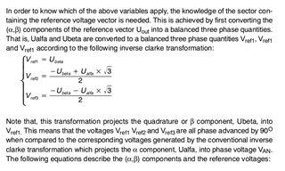
We have the modified inverse-clarke transform,

/* Inverse clarke transformation */                                             \
    Va = v.Ubeta;                                                               \
    Vb = -temp_sv1 + temp_sv2;                                                  \
    Vc = -temp_sv1 - temp_sv2;                                                  \

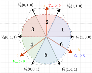
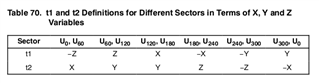
According to the sector determination code:

/* 60 degree Sector determination */                                           \
    if (Va>_IQ(0)) Sector = 1;                                                 \
    if (Vb>_IQ(0)) Sector = Sector+2;                                          \
    if (Vc>_IQ(0)) Sector = Sector+4;

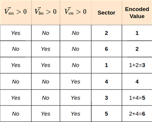
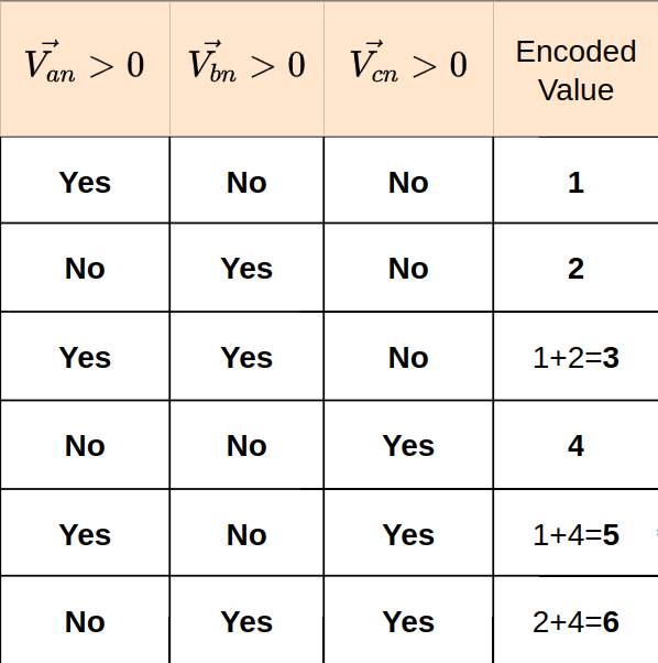
I made this table (sector is initialized as 0):

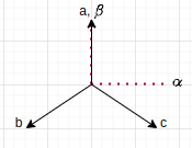
The regions where Va is positive, could be denoted by a semi-circle that's aligned with the phase-a vector. I have tried to visualize the regions as such:

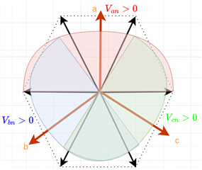
And when only Va>0, according to the table the sector should be 1, but it's actually in the 2nd sector,
When Va>0, and Vb>0, it should be sector 3, and that it is.

Yea, I am confused.

Kindly support, thanks!
Best Regards

  • You may refer to the example code as below since these modules are standard functions for FOC.

    MotorControl SDK: Includes 3-phase PMSM or BLDC based sensorless InstaSPIN-FOC solutions for F28004xC, and 3-phase PMSM based sensored FOC solutions with fast current loop for F2838x, F2837x and F28004x.

    MotorWare Software: Includes InstaSPIN-FOC and InstaSPIN-Motion based 3-phase motor control applications for F2802x, F2805x, and F2806x series, supports ACIM, PMSM and BLDC using FOC.

    controlSUITE: Includes 3-phase BLDC based on hall sensor or sensorless trapezoidal control, 3-phase ACIM/PMSM based sensored FOC with QEP encoder or sensorless FOC.

  • Hello,
    I am working the the PM_Sensorless project, which is given in the controlSUITE SDK itself. That's where I came across the module.

    As mentioned previously, I am unable to figure out the sector determination logic. Conventionally, the atan2 function is used, over the alpha and beta voltage vectors, for the sector determination in SVPWM. But I am assuming this logic has been applied to get rid of the trigonometric computational load.

    But how this logic has been derived, that I am unable to reason out. I have gone through the DMC documentation as well and the given content, turns out, is not enough for me to wrap my head around this. Thus, my attempts at visualisation and the query.

  • As you posted text, there is an SVPWM moulde that calculates the sector, you can the calculated sector directly.  The SVPWM doesn't need any trigonometric computation since it's based on alpha/beta-axis.

    You may take a look at the link below about SVPWM algorithm.

    https://www.switchcraft.org/learning/2017/3/15/space-vector-pwm-intro

  • Thanks for the response.

    In literature, I have mostly seen trigonometric sector determination. The following is an excerpt from the 4th edition of Muhammad H. Rashid's "Power Electronics - Devices, Circuits, and Applications". Point 2. mentions the calculation of θ using the arctan function, and then calculating the sector angle θk from that


    The article you have shared does not delve into sector-determination. It talks about other aspects of the SVPWM technique, and frankly I have come across this article many times in the past. It's always an insightful read haha.

    I am still rather clueless about how this seemingly simple looking code accurately determines the sectors,

    /* 60 degree Sector determination */                                           \
        if (Va>_IQ(0)) Sector = 1;                                                 \
        if (Vb>_IQ(0)) Sector = Sector+2;                                          \
        if (Vc>_IQ(0)) Sector = Sector+4;

    I must be missing something very trivial, and it's gonna be an "eureka" moment for sure. I hope it happens soon.

    Best Regards
    Aarav

  • I think I have figured it out. Two corrections first of all:

    1. I have arranged the abc-vectors in the negative phase-sequence, so that adds to the confusion. Code has been prepared according the positive phase-sequence, which is the standard representation.
    2. The regions where each Va Vb and Vc is positive, will actually be aligned with the diagonals of the hexagon. The semicircle's 180 degrees will perfectly align with the 180 degrees of the 3 sectors of the hexagon, like so:

    One can see why the inverse clarke has been modified to add a shift of 90 degrees, much more clearly now.

    The sector-determination algorithm doesn't directly give us the sectors. It gives us numbers, which we then map to sectors. I made this table, with the help of the diagram (based on the modified inverse clarke-transform) :

    This step is not clear in the code, as the encoded values of the sectors are directly taken into the switch-statement. So the encoded sector 1 in the switch-case statement, actually has the dwell periods for sector-2. Encoded sector 5, will have the dwell periods of sector-3. One can verify this by going through the DMC_Soft_Lib_Documentation, page 201.

    Edit: t2 for sector-3 is actually "-Y"

    And this is the switch statement code given in the svgen_dq.h file:

    /* X,Y,Z (Va,Vb,Vc) calculations X = Va, Y = Vb, Z = Vc */                       \
        Va = v.Ubeta;                                                                \
        Vb = temp_sv1 + temp_sv2;                                                    \
        Vc = temp_sv1 - temp_sv2;                                                    \
    /* Sector 0: this is special case for (Ualpha,Ubeta) = (0,0)*/                   \
                                                                                     \
    switch(Sector)                                                                   \
    {                                                                                \
        case 0:                                                                      \
        v.Ta = _IQ(0.5);                                                             \
        v.Tb = _IQ(0.5);                                                             \
        v.Tc = _IQ(0.5);                                                             \
        break;                                                                       \
        case 1:   /*Sector 1: t1=Z and t2=Y (abc ---> Tb,Ta,Tc)*/                    \
        t1 = Vc;                                                                     \
        t2 = Vb;                                                                     \
        v.Tb=_IQdiv2((_IQ(1)-t1-t2));                                                \
        v.Ta = v.Tb+t1;                 /* taon = tbon+t1        */                  \
        v.Tc = v.Ta+t2;                  /* tcon = taon+t2        */                 \
        break;                                                                       \
        case 2:      /* Sector 2: t1=Y and t2=-X (abc ---> Ta,Tc,Tb)*/               \
        t1 = Vb;                                                                     \
        t2 = -Va;                                                                    \
        v.Ta=_IQdiv2((_IQ(1)-t1-t2));                                                \
        v.Tc = v.Ta+t1;                /*  tcon = taon+t1        */                  \
        v.Tb = v.Tc+t2;                /*  tbon = tcon+t2        */                  \
        break;                                                                       \
        case 3:      /* Sector 3: t1=-Z and t2=X (abc ---> Ta,Tb,Tc)*/               \
        t1 = -Vc;                                                                    \
        t2 = Va;                                                                     \
        v.Ta=_IQdiv2((_IQ(1)-t1-t2));                                                \
        v.Tb = v.Ta+t1;                /*    tbon = taon+t1        */                \
        v.Tc = v.Tb+t2;                /*    tcon = tbon+t2        */                \
        break;                                                                       \
        case 4:      /* Sector 4: t1=-X and t2=Z (abc ---> Tc,Tb,Ta)*/               \
        t1 = -Va;                                                                    \
        t2 = Vc;                                                                     \
        v.Tc=_IQdiv2((_IQ(1)-t1-t2));                                                \
        v.Tb = v.Tc+t1;                /*    tbon = tcon+t1        */                \
        v.Ta = v.Tb+t2;                /*    taon = tbon+t2        */                \
        break;                                                                       \
        case 5:      /* Sector 5: t1=X and t2=-Y (abc ---> Tb,Tc,Ta)*/               \
        t1 = Va;                                                                     \
        t2 = -Vb;                    /*    tbon = (1-t1-t2)/2    */                  \
        v.Tb=_IQdiv2((_IQ(1)-t1-t2));                                                \
        v.Tc = v.Tb+t1;                /*    taon = tcon+t2        */                \
        v.Ta = v.Tc+t2;                                                              \
        break;                                                                       \
        case 6:      /* Sector 6: t1=-Y and t2=-Z (abc ---> Tc,Ta,Tb)*/              \
        t1 = -Vb;                                                                    \
        t2 = -Vc;                                                                    \
        v.Tc=_IQdiv2((_IQ(1)-t1-t2));                                                \
        v.Ta = v.Tc+t1;                /*    taon = tcon+t1        */                \
        v.Tb = v.Ta+t2;                /*    tbon = taon+t2        */                \
        break;                                                                       \
    }                                                                                \
    /*  Convert the unsigned GLOBAL_Q format (ranged (0,1)) ->.. */                  \
    /*     ..signed GLOBAL_Q format (ranged (-1,1))*/                                \
    v.Ta = _IQmpy2(v.Ta-_IQ(0.5));                                                   \
    v.Tb = _IQmpy2(v.Tb-_IQ(0.5));                                                   \
    v.Tc = _IQmpy2(v.Tc-_IQ(0.5));

    A single comment line in the code would have saved me a week, but oh well. Hope this helps someone else out.

    Best Regards
    Aarav