This thread has been locked.

If you have a related question, please click the "Ask a related question" button in the top right corner. The newly created question will be automatically linked to this question.

LAUNCHXL-F2800157: CAN Flash Programming Issues - bitrate, sleep_time and EntryAddr configuration - Peak PCAN USB pro Error Status (Red LED)

Part Number: LAUNCHXL-F2800157
Other Parts Discussed in Thread: C2000WARE, TMS320F2800157

Tool/software:

Hello,

We are attempting to flash a LAUNCHXL-F2800157 LaunchPad via CAN using the DCAN Flash Programmer utility from C2000Ware, but experiencing communication issues. Here are the details:
Setup:

MCU: TMS320F2800157
CAN Interface: Peak PCAN USB Pro
Project Path: C:\ti\c2000\C2000Ware_5_04_00_00\utilities\flash_programmers\dcan_flash_programmer\dcan_flash_programmer

Issue:

The Peak USB Pro's status LED is blinking red during transmission attempts, suggesting communication errors. We have reviewed the configuration but uncertain about the optimal settings.


Current Configuration in dcan_flash_programmer.cpp:


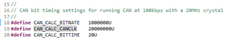
// Bitrate configuration
bitrate = "f_clock_mhz = 20, nom_brp = 40, nom_tseg1 = 16, nom_tseg2 = 3, nom_sjw = 2"; // 100kbps

// Initialization
gStatus = CAN_Initialize(PCAN_USBBUS1, PCAN_BAUD_100K); 

// Sleep timing for F280015x
sleep_time = 10; // in milliseconds


Questions:

  1. Are these bit timing parameters appropriate for the F2800157?
  2. Is the current sleep_time of 10ms appropriate for the F2800157, or should it be adjusted?
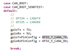
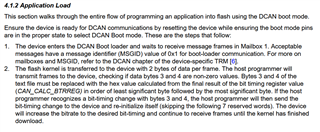
  3. I also came across the following function in flash_kernel_ex5_dcan_flash_kernel.c:
EntryAddr = DCAN_Boot(CAN_BOOT_SENDTEST, 0, 1, 20, WE_Protection_A_Mask, WE_Protection_B_Mask, WE_Protection_UO_Mask);
    I would like clarification on the correct parameters for EntryAddr in this function.

Any guidance on resolving these communication issues would be greatly appreciated.


Additional Info:

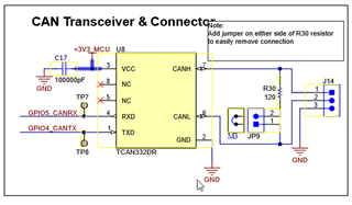
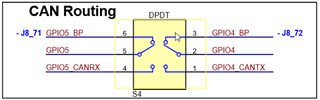
Have verified proper physical connections and termination

  • Hello Taif,

    Thanks for reaching out regarding your issue. Our DCAN expert is currently OOO but I will start looking into this.

    In the meantime,

    For 1) TI provides a Calculator for CAN Bit Timing Parameters to determine optimal bit timing based on the CAN Bus requirements. Please review this tool and verify your specific requirements to determine optimum bit timing parameter config.

    There is also a dedicated app note for DCAN examples here: Programming Examples for the DCAN Module (Rev. A)

    These bit timing values are highly dependent on your transceiver functionality and system/HW layer implementation.

    Would it be possible to try out the Transmit_Recieve CAN example 5 (Linked below for reference) to ensure proper CAN bus operation independent of the DCAN Flash Programmer tool?

    can_ex5_transmit_receive

    For 2 and 3 I will need to follow up with the internal team.

    Thank you for your patience as we continue to address the issue.

    Best Regards,

    Zackary Fleenor

  • Hi Zackary, 

    We really appreciate your reply. As you suggested, we have ensured that example 5 that you referenced, works with our hardware setup. We have verified both the sending and receiving modes successfully. 

    Upon reviewing the TRM (TMS320F280015x Real-Time Microcontrollers), we noticed that the default  TX/RX CAN pins for the microcontroller using CAN BOOT Mode are GPIO7 and GPIO5 respectively (Table 5-36). However, in the documentation for the LaunchPad (C2000 F280015x Series LaunchPad Development Kit, section 3.1.5). GPIO4 and 5 are routed to the transceiver. 

    Do you think this might be causing the CAN communication issue indicated by the RED light during data transfer (during both application and kernel transfer)? To overcome this, we attempted to run the MCU in emulation mode by changing the register values as follows:

    0xD00: 0xFFFF
    0xD01: 0x5AFF
    0xD04: 0x0082

    and the reset the CPU using RUN->Reset->CPU Reset (in CCS).

    Please note that we did it by first running a random blinking led program in Debug mode to access the memory browser in CCS, changed the register values as above, reset the CPU as described, clicked resumed and then attempted to run the 'host' flash programmer again.

    Could you please verify if this is the correct procedure to follow.

    Looking forward to your reply.

    Best regards,
    Taif

  • Hello Taif,

    I have confirmed with the team that this is a known issue with F280015x Launchpads. I am creating a ticket to have a clear statement added in the user guide. This is due to the exact reasoning you mentioned. GPIO4/5 are routed to the transceiver but GPIO7/5 is used by the bootloader.

    The procedure you have followed otherwise is correct.

    Two notes:

    -Ensure the CAN Route Switch (S4) on the LP is set to use the CAN Transciever and not the Boosterpack

    -Ensure the alignment of the flash sections in the linker command file, they need to be on 512-bit boundaries (ALIGN(32))

    Is it possible to use CAN-FD boot? (which is correctly mapped to GPIO4/5)

    Best Regards,

    Zackary Fleenor

  • Hi Zackary,

    Thank you very much for confirming with the team, it clears up some confusion regarding this. 

    We have two more questions before we can attempt the CAN-FD boot.

    1. When you refer to the CAN-FD boot, do you mean the MCAN flash kernel implementation given in the document (Application Note: CAN Flash Programming of C2000 Microcontrollers)? In that case, if you refer to section 5, "TMS320F2800157" is NOT mentioned as a supported device. 

    Moreover, the said flash kernel is also not available in the C2000Ware, maybe you could please provide some clarification on this. (Although, please note that the file named 'flash_kernel_ex5_dcan_flash_kernel.c' has the title in the comments as 'TITLE:   MCAN Flash Kernel Example for F280015x', which might be a mistake).
     
    2. The linker file for the dcan flash kernel is attached but the flash sections could not be identified and so the ALIGN(32) directive was added to all the lines in the 'SECTIONS' area of the linker file. Could you please take a look and let us know if it is the correct way to do this? (Note: File extension was changed from .cmd to .txt so that it could be attached).

    Thanks again, and looking forward to your reply.

    /cfs-file/__key/communityserver-discussions-components-files/171/280015x_5F00_generic_5F00_ram_5F00_lnk.txt

    Best regards,
    Taif

  • Hi Taif,

    1. When you refer to the CAN-FD boot, do you mean the MCAN flash kernel implementation given in the document (Application Note: CAN Flash Programming of C2000 Microcontrollers)? In that case, if you refer to section 5, "TMS320F2800157" is NOT mentioned as a supported device. 

    Yes, CAN-FD and MCAN are used interchangeably in that application note.

    The can_flash_programmer found in C2000Ware is for MCAN boot and dcan_flash_programmer is for CAN boot.

    Moreover, the said flash kernel is also not available in the C2000Ware, maybe you could please provide some clarification on this. (Although, please note that the file named 'flash_kernel_ex5_dcan_flash_kernel.c' has the title in the comments as 'TITLE:   MCAN Flash Kernel Example for F280015x', which might be a mistake).

    Unfortunately, we don't offer an MCAN flash kernel example for F280015x devices, only a CAN/DCAN flash kernel.

    You have two possible options (physical or software modification required) if you wish to use CAN or CAN-FD boot on an F280015x LaunchPad:

    1. You can short GPIO7 (CANTXA) and GPIO5 (CANRXA) directly to the on-board CAN Transceiver & Connector, and use CAN boot. The CAN expert is out of office until next week, but I can provide more details if you're interested in this method. From the schematic:
    2. You can attempt CAN-FD boot using the can_flash_programmer with the "-d f28p55x" flag, as well as modifying the F280015x DCAN flash kernel to use CAN-FD peripheral communication. No physical modification to the LaunchPad is necessary.
    2. The linker file for the dcan flash kernel is attached but the flash sections could not be identified and so the ALIGN(32) directive was added to all the lines in the 'SECTIONS' area of the linker file. Could you please take a look and let us know if it is the correct way to do this? (Note: File extension was changed from .cmd to .txt so that it could be attached).

    You only need to add the 512-bit boundary align directive to Flash sections. Since the DCAN flash kernel executes in RAM, no ALIGN directive needs to be added. In your application linker command file (which will be loaded into the flash by the flash kernel executing in the RAM), you'll need to add the ALIGN directive for all initialized flash sections.

    Please let me know if anything is unclear!

    Best,

    Matt

  • Hi Matt, 

    Thank you very much for getting back to us. 

    We will try the boot via the CAN-FD method that you suggested. In the meantime, if you could provide more details for the hardware modification method, that would be helpful. Thanks!

    Best regards,
    Taif

  • Hi Taif,

    From the F280015x LaunchPad Schematic:

    You'll have to make the following connections to S4 for GPIO7 to replace GPIO4 in the routing to the CAN transceiver:

    1. Solder GPIO5 (J8_71) to GPIO5_CANRX
    2. Solder GPIO7 (J8_77) to GPIO4_CANTX
    3. Leave CAN routing switch as set in schematic (to BP)
      1. This will ensure GPIO4 is disconnected

    Best,
    Matt

  • Hi Matt,

    Thank you for your previous help. After implementing your suggested hardware modifications, we can confirm the PCAN-USB Pro's LED is now blinking green during the flash kernel download using the dcan_flash_programmer.

    However, we still need clarification on the correct parameter values for the DCAN_Boot function in flash_kernel_ex5_dcan_flash_kernel (as during the application firmware download phase, the LED still blinks RED):

    EntryAddr = DCAN_Boot(CAN_BOOT_SENDTEST, 0, 1, 20,
    WE_Protection_A_Mask, WE_Protection_B_Mask, WE_Protection_UO_Mask);

    Specifically:

    1. What should the CAN_BOOT_SENDTEST value be when using GPIO pins 5 and 7?
    2. Is '20' the correct frequency value for the F2800157 device?

    Best regards,
    Taif

  • Hi Taif,

    What should the CAN_BOOT_SENDTEST value be when using GPIO pins 5 and 7?

    You can keep the DCAN_Boot() bootMode parameter as CAN_BOOT_SENDTEST, but make sure you use BOOTDEF 0x82.

    SENDTEST boot modes won't have a 10 second timeout waiting for CAN frames, but will use the same GPIO assignments as their normal (0x02, 0x22, 0x42, 0x62) boot option counterparts.

    You can verify in DCAN_Boot.c that CAN_BOOT_SENDTEST will configure GPIO7/GPIO5 correctly to be used as CAN TX/RX (ignore the comments):

    Is '20' the correct frequency value for the F2800157 device?

    In "device.h", uncomment and use #define USE_PLL_SRC_INTOSC on line 241. Comment out #define USE_PLL_SRC_XTAL

    Also, set the switchToXTAL parameter in the DCAN_Boot() to "0" to ensure INTOSC is used.

    At power-up, the device boot ROM is clocked from an on-chip 10MHz oscillator (INTOSC2). This value needs to be set as the primary internal clock source in the flash kernel and is the default clock at reset.

    Lastly, after generating the flash kernel txt file, open it in a text editor and change bytes 3-4 to be “C0 7A”. These bytes contain metadata to configure the bitrate of the CAN bus.

    Here's an example:

    As per the CAN Flash Programming Guide:

    Why "C0 7A"? These values correspond to the following CAN_CALC settings found in bootloader_can_timing.h:

    Best,
    Matt