This thread has been locked.

If you have a related question, please click the "Ask a related question" button in the top right corner. The newly created question will be automatically linked to this question.

LAUNCHXL-F28P65X: MCU solution for sensored motor inverter

Part Number: LAUNCHXL-F28P65X
Other Parts Discussed in Thread: SYSCONFIG, TMDXIDDK379D, DESIGNDRIVE

Tool/software:

Hello TI,

I’m build a 20kW Inverter for PMSM, which I have to test. I’m now looking for an MCU and control software.

Motor: ME1507 IPM
Encoder: Sin/Cos without index
Vmax = 50-70V
Imax = 300A

I worked a lot with Instaspin and the F28069. The easiest way for me I think would be to use this MCU and make a hardware for the Sin/Cos Encoder and just add the Sin/Cos library.

But if I want to use a newer MCU like the F28P65, F28388D or maybe F280039c, what would you suggest as starting point? I only need sensored-FOC (sensorless additionally is a nice to have). I also would like in this case use the POSMGR for the sin/cos interface.

That is what I found for the F28P65 which I would prefer as MCU:

1. tidm_02017_2w_traction_inverter. The code looks clear, but I didn’t find any mor precisely documentation about the code. Is there any? Does this code work properly? Here I would add the POSMGR initialization with the sysconfig tool right?

2. tida_010936_ganhfmd, tmdxiddk379d and servo_drive_with_can are DesignDrive based. I’ve never worked with DesignDrive, how difficult is it to get into this? Here I would add the POSMGR initialization in the source code?

Another idea would be to use Matlab or Plecs. For Matlab I found this, “Generate Motor Control Models for Selected Algorithm and Hardware”. I’ve worked with Matlab but never with the C2000 Blockset. Is it possible to add the POSMGR with Sin/Cos interface in this example? I found an example for the F280049c and the POSMGR for Matlab. Is it for the F28p65 also so easy to implement?

At the moment this is just for testing the inverter, a reliable implementation will be done later.

Any suggestions would be very nice, best regards,
Daniel

  • Hi Daniel,

    I will forward this to another expert to offer guidance on your first two questions.

    Regarding your MATLAB question, for MathWorks support, please take a look at the MathWorks FAQ at this link below:

    If you have further questions, the best way to get support on MathWorks products is to contact MathWorks live tech support.

    You can also search for answers or post a question on MATLAB Answers C2000 forum. Additionally, there is info on MathWorks support C2000 in Documentation and Examples.

    Best Regards,

    Allison

  • Hello Allison,

    thank you for your response. I think I will try both a C-Code implementation and Matlab.

    I would like to use the example “Generate Motor Control Models for Selected Algorithm and Hardware” because I didn’t find another that matches the F28P65. I could also use the F28379 for example. For the F28379 I found this, https://de.mathworks.com/help/mcb/gs/foc-pmsm-using-quadrature-encoder.html.


    I think I could get I work with “Generate Motor Control Models for Selected Algorithm and Hardware”, is there any detailed documentation?

    Which example would you suggest?

    Do you have any examples of a SinCos Encoder implementation for Simulink? I didn’t find any.

    Are in these examples only two currents measured? Is it somehow possible to change this to three currents?

    And how is the execution speed of the application?

    Best regards,
    Daniel

  • Hello Ti,

    I have an additional question, I looked a bit at the SinCos Library, I saw the this requires an index pin, but my sensor does not have any. So, I think, I can’t use it right?

    What would you suggest in this case for the implementation? The sensor used in my motor does have an offset, so the POSMGR does not make any sense I think, I will build my own preprocessing circuit. And sensor only provides sine and cosine with and common ground.

    I’ve never worked with these kinds of sensors, do you have any hints for the implementation, like errors in amplitude or something? I saw that the QEP can be combined with the SinCos Encoder, is this only for speed measurements or are there other advantages? (In the case I have no index signal)

    Best regards,
    Daniel

  • Hi Daniel,

    For QEP / SinCos encoder, index is an optional signal to help you locate some absolute location of the motor in a incremental encoder. If your encoder does not offer an index signal, you can normally find 0 degree / d axis by doing an alignment of the motor shaft each time you power up the drive by feeding a constant current in from A phase and out from B/C phase (set angle to 0 and give constant Id in FOC), and program this angle as zero angle in the QEP register.

    Regarding SinCos encoder, since the frequency of the sin waveform will be high when you spin the motor at higher speed and your ISR will not be able to capture each cycle of the sine wave normally, the normal way of reading a SinCos encoder would be using a analog / digital hybrid method, where you use zero crossing detection to convert the SinCos signal into AB digital waveform and decode it with QEP to get the coarse position (number of line x4 resolution) and use analog reading to get the fine accuracy, then combine these two readings together to get a full position result. You need to take care of the misalignment of analog and digital reading by detecting quadrant jump in result and compensate the error.

    Han

  • Hello Han,

    thank you for your answer, I read today the sin/cos lib carefully, now I know what you mean. I checked the sensor of the motor again, this is no normal encoder I think, I do have only one wave per revolution. Today I tried already an implementation, which works not so bad. I adapted the slow speed part of the sin/cos library. I thought I have to do it like the sin/cos lib where encoder has more wave per revolution.  

    But what about the example templates, which one would you suggest, I really like the tidm_02017_2w_traction_inverter, because it is everything inside I need at the moment, looks short and clear. But there is no detailed description about the code or a sysconfig explanation?

    @Allison, I solved the part with the encoder, don’t need an example anymore. But answers for the other questions would be nice.

    Best regards,
    Daniel

  • Daniel,

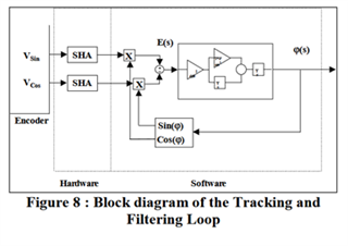
    Are you having some type of inductive / magnetic position sensor with sin/cos feedback for 1 cycle per revolution? In this case, you only need to bring these two signals to ADC and do a PLL / ATAN type of decoding for the position information.

    Han

  • Hello Han,

    yes, it is a magnetic encoder with only one sin cos wave cycle per revolution.

    I implemented it similar to the sin/cos library. What do you mean by PLL? (is this instead of ATAN?)

    I found this in a paper, but I’m not exactly sure what you mean: (www.analog.com/.../452913422000_sin_encoder.pdf)

    I also found a thread, on a PLL for a resolver in this thread: https://e2e.ti.com/support/microcontrollers/c2000-microcontrollers-group/c2000/f/c2000-microcontrollers-forum/1265821/tms320f28388d-back-to-question-on-parameters-used-for-resolver-i-f-in-digital-power-sdk-project-tidm-02009/4867154?tisearch=e2e-sitesearch&keymatch=PLL%2520AND%2520resolver%2520AND%2520motor#4867154

    Is there an advantage using this method? Do you have any resources or references for additional information on this topic?


    This is how I implemented it in Matlab so far, every turn, I look for the max an min values of the sin cos waves to calculate the offset. This is my basic idea, what do you say about this?


    Then I subtract the offset and calculate the angle with atan2. I will add an amplitude correction later.


    Best regards,
    Daniel

  • Hello Ti,

    the SinCos Encoder Part works for me now. I do not have further questions about this, of course if you have some additional thoughts on that, please say.

    What would be very nice if you could answer my questions about what software would you suggest as a starting point for sensored FOC?

    There is this from the 2kW traction inverter and the other that are based on DesignDrive.

    I don’t know if the universal lab makes sense, because there are a lot of things for sensorless FOC with I don’t need.

    Best regards,
    Daniel