This thread has been locked.

If you have a related question, please click the "Ask a related question" button in the top right corner. The newly created question will be automatically linked to this question.

TMS320F28377S: C2000WARE / TMS320F28377S: Assistance Needed for PWM6A Output Issue on TMS320F28377S

Part Number: TMS320F28377S
Other Parts Discussed in Thread: C2000WARE

Tool/software:

Hello,

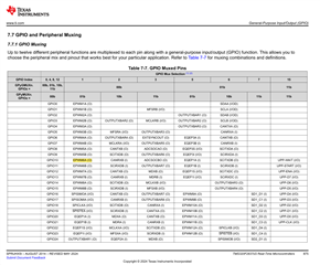
The schematic below shows the control board I am using, which includes the TMS320F28377S. As you can see in the diagram, the board is designed to use EPWM6A and beyond.

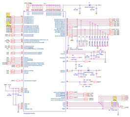
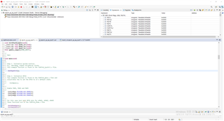
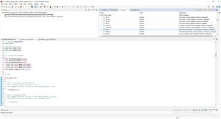
Among the examples provided in TI's C2000Ware, the epwm_up_aq example only utilizes EPWM1 to EPWM3. To adapt this for my needs, I modified the epwm_up_aq_cpu01.c file to use only EPWM6A, as shown below. (However, I did not make any changes to other files such as F2837xS_Gpio.c or F2837xS_EPwm.c.)

=====================================================================================================================================================================

#include "F28x_Project.h"

#define EPWM6_TIMER_TBPRD 2000 // Period register
#define EPWM6_MAX_CMPA 950
#define EPWM6_MIN_CMPA 50
#define EPWM6_MAX_CMPB 1950
#define EPWM6_MIN_CMPB 1050

EPWM_INFO epwm6_info;
void InitEPwm6Example(void);
__interrupt void epwm6_isr(void);

void main(void)
{
InitSysCtrl();
CpuSysRegs.PCLKCR2.bit.EPWM6=1;
DINT;
InitPieCtrl();
IER = 0x0000;
IFR = 0x0000;
InitPieVectTable();

EALLOW; // This is needed to write to EALLOW protected registers
PieVectTable.EPWM6_INT = &epwm6_isr;
EDIS; // This is needed to disable write to EALLOW protected registers

EALLOW;
CpuSysRegs.PCLKCR0.bit.TBCLKSYNC = 0;
EDIS;

IER |= M_INT3;
PieCtrlRegs.PIEIER6.bit.INTx6 = 1;

EINT; // Enable Global interrupt INTM
ERTM; // Enable Global realtime interrupt DBGM

for(;;)
{
asm (" NOP");
}
}

//
// epwm6_isr - EPWM6 ISR to update compare values
//
__interrupt void epwm6_isr(void)
{
//
// Update the CMPA and CMPB values
//
update_compare(&epwm6_info);

//
// Clear INT flag for this timer
//
EPwm6Regs.ETCLR.bit.INT = 1;

//
// Acknowledge this interrupt to receive more interrupts from group 3
//
PieCtrlRegs.PIEACK.all = PIEACK_GROUP3;
}

//
// InitEPwm6Example - Initialize EPWM6 values
//
void InitEPwm6Example()
{
//
// Setup TBCLK
//
EPwm6Regs.TBCTL.bit.CTRMODE = TB_COUNT_UP; // Count up
EPwm6Regs.TBPRD = EPWM6_TIMER_TBPRD; // Set timer period
EPwm6Regs.TBCTL.bit.PHSEN = TB_DISABLE; // Disable phase loading
EPwm6Regs.TBPHS.bit.TBPHS = 0x0000; // Phase is 0
EPwm6Regs.TBCTR = 0x0000; // Clear counter
EPwm6Regs.TBCTL.bit.HSPCLKDIV = TB_DIV2; // Clock ratio to SYSCLKOUT
EPwm6Regs.TBCTL.bit.CLKDIV = TB_DIV2;

//
// Setup shadow register load on ZERO
//
EPwm6Regs.CMPCTL.bit.SHDWAMODE = CC_SHADOW;
EPwm6Regs.CMPCTL.bit.SHDWBMODE = CC_SHADOW;
EPwm6Regs.CMPCTL.bit.LOADAMODE = CC_CTR_ZERO;
EPwm6Regs.CMPCTL.bit.LOADBMODE = CC_CTR_ZERO;

//
// Set Compare values
//
EPwm6Regs.CMPA.bit.CMPA = EPWM6_MIN_CMPA; // Set compare A value
EPwm6Regs.CMPB.bit.CMPB = EPWM6_MIN_CMPB; // Set Compare B value

//
// Set actions
//
EPwm6Regs.AQCTLA.bit.ZRO = AQ_SET; // Set PWM6A on Zero
EPwm6Regs.AQCTLA.bit.CAU = AQ_CLEAR; // Clear PWM6A on event A,
// up count

EPwm6Regs.AQCTLB.bit.ZRO = AQ_SET; // Set PWM6B on Zero
EPwm6Regs.AQCTLB.bit.CBU = AQ_CLEAR; // Clear PWM6B on event B,
// up count

//
// Interrupt where we will change the Compare Values
//
EPwm6Regs.ETSEL.bit.INTSEL = ET_CTR_ZERO; // Select INT on Zero event
EPwm6Regs.ETSEL.bit.INTEN = 1; // Enable INT
EPwm6Regs.ETPS.bit.INTPRD = ET_3RD; // Generate INT on 3rd event

//
// Information this example uses to keep track
// of the direction the CMPA/CMPB values are
// moving, the min and max allowed values and
// a pointer to the correct ePWM registers
//
epwm6_info.EPwm_CMPA_Direction = EPWM_CMP_UP; // Start by increasing
// CMPA & CMPB
epwm6_info.EPwm_CMPB_Direction = EPWM_CMP_UP;
epwm6_info.EPwmTimerIntCount = 0; // Zero the interrupt counter
epwm6_info.EPwmRegHandle = &EPwm6Regs; // Set the pointer to the
// ePWM module
epwm6_info.EPwmMaxCMPA = EPWM6_MAX_CMPA; // Setup min/max
// CMPA/CMPB values
epwm6_info.EPwmMinCMPA = EPWM6_MIN_CMPA;
epwm6_info.EPwmMaxCMPB = EPWM6_MAX_CMPB;
epwm6_info.EPwmMinCMPB = EPWM6_MIN_CMPB;
}

//
// update_compare - Update the compare values for the specified EPWM
//
void update_compare(EPWM_INFO *epwm_info)
{
//
// Every 10'th interrupt, change the CMPA/CMPB values
//
if(epwm_info->EPwmTimerIntCount == 10)
{
epwm_info->EPwmTimerIntCount = 0;

//
// If we were increasing CMPA, check to see if
// we reached the max value. If not, increase CMPA
// else, change directions and decrease CMPA
//
if(epwm_info->EPwm_CMPA_Direction == EPWM_CMP_UP)
{
if(epwm_info->EPwmRegHandle->CMPA.bit.CMPA < epwm_info->EPwmMaxCMPA)
{
epwm_info->EPwmRegHandle->CMPA.bit.CMPA++;
}
else
{
epwm_info->EPwm_CMPA_Direction = EPWM_CMP_DOWN;
epwm_info->EPwmRegHandle->CMPA.bit.CMPA--;
}
}

//
// If we were decreasing CMPA, check to see if
// we reached the min value. If not, decrease CMPA
// else, change directions and increase CMPA
//
else
{
if(epwm_info->EPwmRegHandle->CMPA.bit.CMPA == epwm_info->EPwmMinCMPA)
{
epwm_info->EPwm_CMPA_Direction = EPWM_CMP_UP;
epwm_info->EPwmRegHandle->CMPA.bit.CMPA++;
}
else
{
epwm_info->EPwmRegHandle->CMPA.bit.CMPA--;
}
}

//
// If we were increasing CMPB, check to see if
// we reached the max value. If not, increase CMPB
// else, change directions and decrease CMPB
//
if(epwm_info->EPwm_CMPB_Direction == EPWM_CMP_UP)
{
if(epwm_info->EPwmRegHandle->CMPB.bit.CMPB < epwm_info->EPwmMaxCMPB)
{
epwm_info->EPwmRegHandle->CMPB.bit.CMPB++;
}
else
{
epwm_info->EPwm_CMPB_Direction = EPWM_CMP_DOWN;
epwm_info->EPwmRegHandle->CMPB.bit.CMPB--;
}
}

//
// If we were decreasing CMPB, check to see if
// we reached the min value. If not, decrease CMPB
// else, change directions and increase CMPB
//
else
{
if(epwm_info->EPwmRegHandle->CMPB.bit.CMPB ==
epwm_info->EPwmMinCMPB)
{
epwm_info->EPwm_CMPB_Direction = EPWM_CMP_UP;
epwm_info->EPwmRegHandle->CMPB.bit.CMPB++;
}
else
{
epwm_info->EPwmRegHandle->CMPB.bit.CMPB--;
}
}
}
else
{
epwm_info->EPwmTimerIntCount++;
}

return;
}

//
// End of file
//
======================================================================================================================================================================

Despite completing the debugging process based on the modified file, I am not seeing any output on PWM6A when checking with an oscilloscope.

Could you provide guidance on which files and specific code modifications are required to enable EPWM6A output?

I would greatly appreciate your advice.

Best regards,
Seungsoo Kim

  • Hello Seungsoo,

    A few questions to help debug:

    1. Are you able to run the example unmodified and see the EPWM outputs on your scope?
    2. In the modified project, when you step through the code and check the EPWM6 registers do you see the configurations changing as expected?
    3. When running the modified project, do you see EPWM6 counter actively counting?
    4. Please double check your EPWM6 GPIO initialization. Which GPIOs are you scoping?

    Best Regards,

    Allison

  • 1. The board I am using, which is equipped with the F28377S, utilizes EPWM starting from EPWM6. Therefore, it is not possible to observe EPWM output using the existing example.
    2. I modified the original C2000Ware example file epwm_up_aq by changing only the number from EPWM1 to EPWM6 in the epwm_up_aq_cpu01.c code.
    3. How can I verify whether the EPWM6 counter is increasing?
    4. As shown in the figure below, I want to check the output of EPWM6A, so I am measuring GPIO10 with an oscilloscope.

  • Hello,

    You can check that your EPWM configurations are being programmed correctly and view the counter of EPWM6 changing during runtime by viewing the "Registers" window in CCS.

    Go to "View" > "Registers" > scroll to your EPWM6 registers and use the drop downs to find your EPWM6 TBCTR register. Make sure you have "Continuous Refresh" on during run time so that the register values update live (they will highlight yellow as they change). 

    Please let me know if you are able to view these registers and see your configurations correctly being implemented - you can view the registers as you "Step over" lines of code during your initialization to see the changes being made in the registers accordingly.

    Have you set up your GPIOs so they are configured to output EPWM6? Please verify that the GPIO registers are set up correctly as well. Can you send your intializations?

    Best Regards,

    Allison

  • Hello Nguyen,

    The attached image shows the execution of the epwm_up_aq_cpu01 example from C2000Ware using the F28377S board in Real-Time Mode through Target Configurations.

    As you explained, even after pressing Continuous Refresh, the EPWM1 register values do not update and remain at 0x0000.

    I would greatly appreciate any advice you could provide to resolve this issue.

    Thank you for your time and consideration.

    Best regards,
    Seungsoo Kim

  • Hi Seungsoo Kim,

    Thanks for checking the registers. To clarify, at what point in the code are you checking the registers? Can you please use the "step over" button or set a breakpoint after the lines of code that initialize the EPWM timebase registers and send a screen capture of this? 

    Also, it looks like you are viewing the "expressions" window. Can you please send a snippet of the "Registers" window with the EPWM6 registers expanded and viewable?

    Right now, the EPWM registers you sent are completely empty, meaning perhaps you are configuring a different EPWM or looking at the registers of a different EPWM, you are checking the registers before running through the init, or there is something else going on we need to look into.

    Best Regards,

    Allison

  • Hi Allison

    The previous screenshot I posted was captured after performing the following steps:
    Target Configurations → Launch Selected Configuration → Connect Target → Enable Silicon Real-Time Mode → Resume.

    Additionally, the attached screenshot was taken using the same method, but this time with the Registers window open for better visibility.

    Furthermore, when I try to use the Step Over button, the debugger switches to a window displaying the message:
    "Break at address '0x3ff16e' with no debug information available, or outside of program code."

    Due to this, I am unable to proceed with the Step Over function.

    Best regards,
    Seungsoo Kim

  • Hi Seungsoo Kim,

    When you load the program, does CCS halt at the start of your main() function still? Since you are unable to step through your code, I'm having doubts that your code is running through the initializations properly - that would also explain why you don't see your EPWM getting configured. 

    The message you see in the debug window means that the CPU has gone to an address in the bootrom (0x3ff16a) as indicated by the device memory map found within the F2837xS datasheet (below) - likely in some ITRAP. 

    Can you please run the unmodified C2000ware example and first just make sure you can load and step over the device initializations and see the registers change correctly (no need to scope the pins if you do not have access to them). I want to establish this as a baseline and ensure your setup is working.

    Best Regards,

    Allison

  • Hi Allison,

    When I build the unmodified C2000Ware example, I only see some advice messages, as shown below.

    However, when I go through the steps:
    Target Configurations → Launch Selected Configuration → Connect Target → Enable Silicon Real-Time Mode → Resume,
    I still encounter the same issue where the "Break at address '0x3ff16a' with no debug information available, or outside of program code." message appears.

    Additionally, when I try to use the Step Over button, the debugger switches to the same message, making it impossible to use the Step Over function.

    In your previous advice, you mentioned that, based on the device memory map, the CPU may have fallen into an ITRAP.
    Would modifying the application from a RAM-based configuration to a Flash-based configuration, as suggested in the post below, resolve this issue?

    e2e.ti.com/.../tms320f28379d-running-code-from-flash

    Best regards,
    Seungsoo Kim

  • Hi Seungsoo Kim,

    In your previous advice, you mentioned that, based on the device memory map, the CPU may have fallen into an ITRAP.
    Would modifying the application from a RAM-based configuration to a Flash-based configuration, as suggested in the post below, resolve this issue?

    No, the ITRAP works essentially as a safety mechanism - stopping the CPU if it attempts an illegal instruction or other related issue. This would not resolve the cause of triggering an ITRAP ISR.

    Target Configurations → Launch Selected Configuration → Connect Target → Enable Silicon Real-Time Mode → Resume,

    To clarify, are you able to successfully load your .out file onto the device? After you connect, select load > load program > browse your project and select the ".out" file you generated when you built your project to load it to RAM or FLASH. If you are loading properly, you should be halted at the beginning of your main() after loading.

    Best Regards,

    Allison

  • Hi Allison,

    After building the unmodified C2000Ware example, I specified the epwm_up_aq_cpu01.out file in the Debugging window using the following steps:
    Run → Load → Load Program → Select epwm_up_aq_cpu01.out file
       

    After clicking Resume, a blue block appeared next to the main() function line in the code, as shown in the attached screenshot. (The blue block is only present at the main() function.)

    Does this mean that the .out file was successfully loaded and the execution stopped at the beginning of main()?

    Best regards,
    Seungsoo Kim

  • Hi Suengsoo Kim,

    Yes, that is the confirmation I needed, thank you. Once you get to this point, can you please use the "step over" button to step over the code in your initializations while watching the registers window? Or- per your previous response- as soon as you try to step over the first line, are you seeing the break at address message? Can you try loading and running without enabling real time mode (is there a specific reason you are using this at the moment)?

    Best Regards,

    Allison

  • Hi Allison,

    The attached screenshot was taken after performing the following steps:
    Run → Load → Load Program → Select epwm_up_aq_cpu01.out file and then clicking the Step Over button.

    Unlike before, the previous stop message does not appear anymore.

    However, as you can see in the Registers window, the EPwm1Regs.TBCTR value remains 0x0000, even after clicking Continuous Refresh button.

    One thing I suspect is that the blue block only appears next to the main() function line.
    Since the main() function only contains the following line:

    //
    // Main
    //
    void main(void)
    {
    //
    // Step 1. Initialize System Control:
    // PLL, WatchDog, enable Peripheral Clocks
    // This example function is found in the F2837xS_SysCtrl.c file.
    //
        InitSysCtrl();
    
    //
    // Step 2. Initialize GPIO:
    // This example function is found in the F2837xS_Gpio.c file and
    // illustrates how to set the GPIO to it's default state.
    //
    //    InitGpio();
    
    //
    // Enable PWM1, PWM2 and PWM3
    //
        CpuSysRegs.PCLKCR2.bit.EPWM1=1;
        CpuSysRegs.PCLKCR2.bit.EPWM2=1;
        CpuSysRegs.PCLKCR2.bit.EPWM3=1;
    
    //
    // For this case just init GPIO pins for ePWM1, ePWM2, ePWM3
    // These functions are in the F2837xS_EPwm.c file
    //
        InitEPwm1Gpio();
        InitEPwm2Gpio();
        InitEPwm3Gpio();
    
    //
    // Step 3. Clear all interrupts and initialize PIE vector table:
    // Disable CPU interrupts
    //
        DINT;
    
    //
    // Initialize the PIE control registers to their default state.
    // The default state is all PIE interrupts disabled and flags
    // are cleared.
    // This function is found in the F2837xS_PieCtrl.c file.
    //
        InitPieCtrl();
    
    //
    // Disable CPU interrupts and clear all CPU interrupt flags:
    //
        IER = 0x0000;
        IFR = 0x0000;
    
    //
    // Initialize the PIE vector table with pointers to the shell Interrupt
    // Service Routines (ISR).
    // This will populate the entire table, even if the interrupt
    // is not used in this example.  This is useful for debug purposes.
    // The shell ISR routines are found in F2837xS_DefaultIsr.c.
    // This function is found in F2837xS_PieVect.c.
    //
        InitPieVectTable();
    
    //
    // Interrupts that are used in this example are re-mapped to
    // ISR functions found within this file.
    //
        EALLOW; // This is needed to write to EALLOW protected registers
        PieVectTable.EPWM1_INT = &epwm1_isr;
        PieVectTable.EPWM2_INT = &epwm2_isr;
        PieVectTable.EPWM3_INT = &epwm3_isr;
        EDIS;   // This is needed to disable write to EALLOW protected registers
    
    //
    // For this example, only initialize the ePWM
    //
        EALLOW;
        CpuSysRegs.PCLKCR0.bit.TBCLKSYNC = 0;
        EDIS;
    
        InitEPwm1Example();
        InitEPwm2Example();
        InitEPwm3Example();
    
        EALLOW;
        CpuSysRegs.PCLKCR0.bit.TBCLKSYNC = 1;
        EDIS;
    
    //
    // Step 4. User specific code, enable interrupts:
    //
    // Enable CPU INT3 which is connected to EPWM1-3 INT:
    //
        IER |= M_INT3;
    
    //
    // Enable EPWM INTn in the PIE: Group 3 interrupt 1-3
    //
        PieCtrlRegs.PIEIER3.bit.INTx1 = 1;
        PieCtrlRegs.PIEIER3.bit.INTx2 = 1;
        PieCtrlRegs.PIEIER3.bit.INTx3 = 1;
    
    //
    // Enable global Interrupts and higher priority real-time debug events:
    //
        EINT;  // Enable Global interrupt INTM
        ERTM;  // Enable Global realtime interrupt DBGM
    
    //
    // Step 5. IDLE loop. Just sit and loop forever (optional):
    //
        for(;;)
        {
            asm ("  NOP");
        }
    }
    

    Could this be the reason why EPwm1Regs.TBCTR remains at 0x0000?
    Does my assumption seem correct?

    Additionally, the reason I used Real-Time Mode is that, as a beginner in CCS, I referred to YouTube videos and blog posts, which led me to use this mode.

    Best regards,
    Seungsoo Kim

  • Hi Seungsoo Kim,

    Stepping over the SysCtrl init should take you to the next line of code with the CPU remaining halted. In the image you provided, the CPU is seen "running". Can you please step into the SysCtrl init and then step over the code there to ensure they are being executed (watch the sysctrl registers while you step over to ensure the lines are being configured properly). Are you able to execute the systrl initialization?

    To clarify, are you unable to run any of the C2000ware examples? Are you using a launchpad for this?

    If you are new to CCS and C2000, I would also suggest checking out the C28x Academy. There are exercises there that walk through how to set up a project and run it, as well as validate it.

    Best Regards,

    Allison

  • Hi Allison,

    I was able to resolve the issue thanks to your help.

    While debugging with the step over function, I found that the code execution was stuck at the following line in F2837xS_SysCtrl.c:

                while(ClkCfgRegs.SYSPLLSTS.bit.LOCKS != 1)

    After investigation, I discovered that the oscillator connected to the TMS320F28377S was not properly soldered. Once I re-soldered the component, the code executed as expected and I was able to confirm the EPWM6 signal.

    Thank you so much for your support. I really appreciate it!

    Best regards,
    Seungsoo Kim