LAUNCHXL-F28379D: Red dot with CPU halted in the debug session

Part Number: LAUNCHXL-F28379D

Tool/software:

I worte a code to configure EPWM module. I was running few weeks ago. I'm facing the following issue after updating the CCS to 21.1.1. 

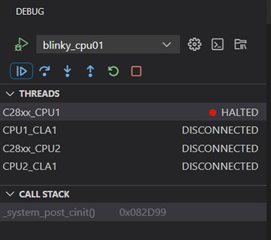
When I try to run the debug session, the red dot appears, as shown below. What is the meaning of this indicator..?

When I click on continue button, nothing happens and the following window appears:

The following window appears when I click 2nd time:

Could you please help me with the solution to the above problem.?

Please find below the following code for your reference:


//#include "F2837xD_device.h"
//#include "F28x_Project.h"

__cregister unsigned int IER;
interrupt void cri_pk_tr(void);

void main(void)
{
    // step1 : GPIO Configuration for EPWM1A & EPWM1B Module
        // GPIO0 -> EPWM1A; Pin - 40
        // GPIO1 -> EPWM1B; Pin - 39
        __asm(" EALLOW");
        *(volatile unsigned int *) 0x7C06 = 0x0005;
        __asm(" EDIS");

    // step2 : PLL Setup & clock routing to EPWM & ADC
        __asm(" EALLOW");
        // Clock Source Select
        *(volatile unsigned int *)0x5D208 = 0x0001;
        // Select system clock divider
        *(volatile unsigned int *)0x5D222 = 0x0001;
        // Set PLL Multiplier Integer and fractional part
        // f_PLLSYSCLK = f_OSCCLK*(SYSPLLMULT.IMULT + SYSPLLMULT.FMULT)/SYSCLKDIVSEL.PLLSYSCLKDIV
        *(volatile unsigned int *)0x5D214 = 0x0028;
        // Select PLL as clock source & enable it
        *(volatile unsigned int *)0x5D20E = 0x0003;
        //CPU clk enable for EPWM
        *(volatile unsigned int *)0x5D326 = 0x0001;
        //CPU clk enable for ADCA
        //*(volatile unsigned long *)0x5D33C = 0x0001;
        __asm(" EDIS");

    // step3 : EPWM Module setup
        __asm(" EALLOW");
        //Turn off time base sync
        *(volatile unsigned int *)0x5D323 = 0x0000;
        // Initialization
        *(volatile unsigned int *)0x4004 = 0x0000; // reset time base counter
        *(volatile unsigned int *)0x4061 = 0x0000; // reset phase register
        *(volatile unsigned int *)0x4063 = 0x09C4; // load TBPRD (for 20 kHz)
        // Configure time base module
        *(volatile unsigned int *)0x4000 = 0x0002;
        // Configure Counter Conpare
        *(volatile unsigned int *)0x4008 = 0x000A;
        *(volatile unsigned int *)0x406B = 0x0000; // Initialize Compare A register (change in runtime)
        // Configure Action Qualifier
        *(volatile unsigned int *)0x4040 = 0x0090;
        *(volatile unsigned int *)0x4042 = 0x0060;
        // Configure Deadband
        *(volatile unsigned int *)0x400C = 0x000B;
        *(volatile unsigned int *)0x4051 = 0x0030;
        *(volatile unsigned int *)0x4053 = 0x0030;
        // Configure Event Trigger
        *(volatile unsigned int *)0x40A4 = 0x000B;
        *(volatile unsigned int *)0x40A6 = 0x0001;
        // Turn on time base sync
        *(volatile unsigned int *)0x5D323 = 0x0004;
        __asm(" EDIS");

    // step4 : Route interrupt to the CPU
        __asm(" setc INTM");
        *(volatile unsigned int *)0x0CE0 = 0x0001;
        __asm(" EALLOW");
        *(volatile unsigned int *)0x0D60 = &cri_pk_tr;
        __asm(" EDIS");
        *(volatile unsigned int *)0x0CE6 = 0x0001;
        IER = 0x0004;
        __asm(" clrc INTM");

    while(1){}

}


interrupt void cri_pk_tr(void)
{      
        *(volatile unsigned int *)0x406B = 0x0100; // updating Compare A register

        *(volatile unsigned int *)0x40AA = 0x0001; //clearing EPWM flag bit

        *(volatile unsigned int *)0x0CE1 |= 0x0004; // clearing PIEACK bit for group 3
};
  • Hi Hitesh,

    This red dot is just a new visual on the CCS to show case that your CPU is halted.

    Best,

    Ryan Ma

  • Hi Ryan, 

    Thanks for clarification. But I'm still not getting the output PWM waveforms. It was working with the older version of the CCS software.

  • Hi Hitesh,

    In order for you to get PWM waveforms. Please ensure your TBCLKSYNC = 1, you have a TBPRD set, CMPA/B values set, and AQ actions set for each event under AQCTLA/B.

    Best,

    Ryan Ma

  • Hi Ryan,

    It's already set as mentioned in the code I posted. 

            // Turn on time base sync
            *(volatile unsigned int *)0x5D323 = 0x0004;
  • Have you verified TBPRD, CMPA/B values, and AQCTLA/B settings?

  • These settings are already verified. It was working with the previous ccs version. Could you please look at the following images.. It's showing "boot28.asm" was not found.

  • I replaced " *(volatile unsigned int *)0x0D60 = &cri_pk_tr; " with " PieVectTable.EPWM1_INT = &cri_pk_tr; " and the code started working. I'm essentially doing the same thing. How to handle this if I don't want to use register structure and bitfield ?

           
  • Hi Hitesh,

    What's the value at the 0x0D60 address before and after replacing? Do they both have the same value at that address?

    Check to see if PieVectTable.EPWM1_INT is the address 0x0D60 and if the value at this address is the same before and after.

    If they are not, maybe due to the data type you have implicitly declared

    Best,

    Ryan Ma

  • Hi Ryan,

    I just noticed in TRM that the address of ISR is 22-bit. Hence, 'long' is the right datatype to use..My code actually worked with the following..

    *(volatile unsigned long *)0x0D60 = (unsigned long)&cri_pk_tr;

    Thanks for you time..