This thread has been locked.

If you have a related question, please click the "Ask a related question" button in the top right corner. The newly created question will be automatically linked to this question.

TMS320F28075: INTOSC2 not working

Part Number: TMS320F28075
Other Parts Discussed in Thread: C2000WARE

Tool/software:

We have custom boards with the said uC. We were testing total 5 prototype boards. We want to run the uC wiht 120MHz clock which is derived from PLL with INTOSC2 as clock source. This is selected based on TRM.

But when we tested, we observed that only 1-2 boards correctly lock the PLL. 1 board intermittently lock PLL and 2 boards doesn't lock at all.

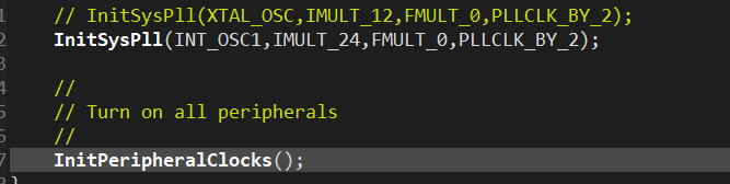
However, when we switched PLL clock source to INTOSC1 all boards work correctly. PLL gets locked without fail.

We are using InitSysPll library function to enable the PLL.

Regards,

Akshay Dandekar

  • Akshay,

    Both INTOSC1 and INTOSC2 should be valid clock sources for the device, but INTOSC2 is the default clock source from power up, and based on the clock control logic it is preferred internal clock to use for the system/PLL clock(as you mentioned based on the TRM).  There's no reason that INTOSC2 should have any issues here.

    I'd like to confirm you are using the C2000Ware drivers to set up the clock sources/lock the PLL/etc; also can you confirm which version of C2000Ware you have installed on your machine?

    Best,
    Matthew

  • Hello Matthew,

    C2000Ware_v5.04.00.00

    -----------------------------------------------------------------------------------------------------------------

    We are using "InitSysPll" As shown in below image,

    Here, If we switch to INT_OSC2, code doesn't work on all boards. Some boards it gets stuck.

    Best Regards,

    Akshay

  • Akshay,

    I may need to try this on some of my devices to see if I can reproduce, just to re-iterate this is not expected from our side as INTOSC2 is the default clock from reset/power on.

    Is the code getting stuck inside the InitSysPLL function itself?  If possible could you step into that function to see on the "failing" devices where things go wrong?

    Some HW questions

    1) Is this on TI EVM(LaunchPad or controlCARD), or custom PCB?  

    2) For the good/bad devices can you comment on the qty of the total build and how many are failing

    3) Is this a production run or proto build? 

    4) If a reasonable amount of units, would it be possible to reply back with the digits in the highlighted portion of the top side below for both failing/not failing?

    Best,

    Matthew

  • Hello Matthew,

    Find answers in blue

    --------------------------------------------------

    I may need to try this on some of my devices to see if I can reproduce, just to re-iterate this is not expected from our side as INTOSC2 is the default clock from reset/power on.

    >>> INTOSC1 always works.

    Is the code getting stuck inside the InitSysPLL function itself?  If possible could you step into that function to see on the "failing" devices where things go wrong?

     >>> We could not figure out whether it is InitSysPLL or any other function. But we downloaded a single blinky code to the board. And we power cycle boards multiple times and checked whether the LED blinks or not.

    Below is the image that describes the board number and whether the LED blinked or not

    But I cannot confirm for sure that this is the place where it is stuck. But definitely it is reaching till InitSysPLL and then getting reset. We added code to turn another LED on, just before InitPLL. When it doesn't work that LED blinks really fast. meaning controller is reset continuously.

    Attaching code snipped for GPIO

    Some HW questions

    1) Is this on TI EVM(LaunchPad or controlCARD), or custom PCB? 

    >>> It is a custom board

    2) For the good/bad devices can you comment on the qty of the total build and how many are failing

    >> We have total 5 prototype boards, out of which 3 boards are not working correctly (Board number 1 in the above table was not working earlier, but when we tested today, it is working as of today)

    3) Is this a production run or proto build? 

    >> It's a proto build

    4) If a reasonable amount of units, would it be possible to reply back with the digits in the highlighted portion of the top side below for both failing/not failing?

    >>> Highlighted digits on IC :  YFC - 3AC4H8W

    Best,

    Akshay

  • Akshay,

    Can we check the integrity of the VDD(1.2V) supply on the PCBs?  

    1)Can you comment if you are using internal VREG to supply 1.2V(VREGENZ pin tied to VSS) or supplying 1.2V externally

    2)Can you also comment on the capacitor network on the VDD supply, values, locations, etc

    3)Let's also check the INTOSC2OFF bit to make sure it is not set https://www.ti.com/document-viewer/lit/html/SPRUHM9H#GUID-20211103-SS0T-HDTF-BWQ0-HCKKTBW35XCF/HARMONY_SYSCTRL_CLK_CFG_REGS 

    In terms of debug of the failing boards we can bring out INTOSC2 to the XCLKOUT pinmux and check it with a scope; here are the steps:

    1)Configure the mux for GPIO73 to bring out XCLKOUT to this pin

    2)Configure the XCLKOUT source(INTOSC2) and set the divider to /1 https://www.ti.com/document-viewer/lit/html/SPRUHM9H#GUID-A4DAF831-22A0-45DC-86F7-AD28C5199440/TITLE-SPRUHM8SPRUHM83001

    There should be a driverLIB function for #2 above, with masks for each clock source

    We expect to see INTOSC2(and INTOSC1) be at 10MHz natively.  You can also change the XCLKOUT source to be INTOSC1 and confirm it as well, as a comparison for INTOSC2.

    Best,
    Matthew