This thread has been locked.

If you have a related question, please click the "Ask a related question" button in the top right corner. The newly created question will be automatically linked to this question.

TMS320F28388D: Wow can I make my own PDO definitions?

Genius 17425 points

Tool/software:

Hi Experts,

Customer is working with TI f28p65x launchpad and using ethercat communication with Beckhoff c603. The example for f28p65x_cpu1_dc_eepromemu_echoback is working:

Question is how can I make my own PDO definitions? In the example, the -> ethercat_subdevice_ssc_and_demo_setup.exe is given which created -> f28p65x_ssc_config.xml which is imported in the SSC tool to create the F28P65x CPU1 EtherCAT SubDevice.xml and C files.

Should I manually edit the f28p65x_ssc_config.xml and then import in the SSC tool (or) is there another way?

About this post from E2E:

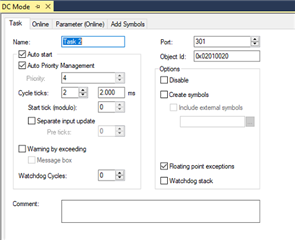
As I understand the thread, I have to load the xml config in SSC tool and create a new excel sheet with my definitions and generate the files. Is this the right workflow? Additionally, how can I change the Distribution Clock Frequency?

Do I need to set it in the launchpad or the master Beckhoff PC?

Thank you.

Regards,

Archie A.

  • Hi Archie,

    The information in that prior E2E is good and valid. You will need to create and edit the excel sheet for the SSC tool. Also see the PDF below for details and references.

    https://download.beckhoff.com/download/document/io/ethercat-development-products/ethercat_slave_design_quick_guide.pdf

    Additionally, how can I change the Distribution Clock Frequency?

    Do I need to set it in the launchpad or the master Beckhoff PC?

    You want to change how often DC synchronizes the devices or something else? This would be done on the Beckhoff PC side, changing the task period time. There is of course a max frequency for this (think it's 'MIN_PD_CYCLE_TIME' in SSC tool).

    Best,

    Kevin

  • Hi Archie,

    Sharing an example excel sheet I have for expanding the amount of data.

    F28P65x CPU1 eCAT Echoback Data Expand v1.xlsx

    Best,

    Kevin

  • Hello Kevin,

    Thank you very much for your support.

    Follow up question - How to set the Distributed Clock Cycle Time already in the Slave? If it is already set in the example, where to find the related code where the cycle time is set to for example "X" nano seconds?

    73,
    Archie A.

  • Hi Archie,

    Cycle time can be changed in TwinCAT side once you set-up a task. I'd suggest referencing the AM26x material below, it's pretty clear and the same procedure for C2000.

    https://software-dl.ti.com/mcu-plus-sdk/esd/AM263X/08_02_00_28/exports/docs/api_guide_am263x/ETHERCAT_SLAVE_DEMO_TWINCAT.html#ETHERCAT_SLAVE_DEMO_TWINCAT_DC_MODE_TESTING 

    Best,

    Kevin

  • Hi Kevin,

    Thank you.

    The example is working as expected. I have been integrating the eeprom emulation from flash bank1 with my already developed code. The linker file has been changed. I tested the new linker file with the example and it works. But when I add my other code in the project, the HW_init (or ESC_initHW) is failing at :

    while(ESC_loadedCheckEEPROM() != ESC_EEPROM_SUCCESS)
    {
    eepromTimeOut--;

    //
    // On time out, return fail
    //
    if(eepromTimeOut == 0U)
    {
    return(ESC_HW_INIT_FAIL); // -> returning here
    }
    }

    The I2C seems to be initialized and I can see interrupts enabled. I went through the ESC_loadedCheckEEPROM() funciton chain but cannot make sense of what could be going wrong. Do you have some advice or hints?

    73,
    Archie A.

  • Hi Archie,

    Your ESC EEPROM is not loaded or getting read properly for some reason. There are some minimum bytes that need to be programmed / read for it to work.

    Are you trying to use the EEPROM emulation solution itself instead of standard I2C EEPROM programming managed by the ECAT Master device?

    Best,

    Kevin

  • Hi Kevin,

    Thank you for your support.

    We are using standard I2C managed by ESC with launchxl f28p65x. I have been trying to debug for 4 days but I cannot understand what is going on because the example itself is working and I am using the same initialization and only integrated some of my code. Then the ECAT error leds starts to flicker right after ESC_resetESC();

    I have looked at the System clock frequency in the example with:
    {
    volatile uint32_t lowspd_sysclk_hz = SysCtl_getLowSpeedClock(DEVICE_SETCLOCK_CFG);
    volatile uint32_t sysclk_hz = SysCtl_getClock(DEVICE_SETCLOCK_CFG);
    asm(" ESTOP0");
    }

    Strangely the sysclk_hz value is around 71 MHz. But in my code it was 200MHz. Is there something that I could be doing wrong with the system clock and peripheral clock frequencies?

    Any guidance is highly appreciated.

    73,
    Archie A.

  • Hi Archie,

    Strangely the sysclk_hz value is around 71 MHz. But in my code it was 200MHz. Is there something that I could be doing wrong with the system clock and peripheral clock frequencies?

    Is the code getting stuck in that clock check function? Did you change anything related to the clock config to not make it 200MHz? 71MHz seems like an odd #.

    You will need to program a new ESI file to the EEPROM after re-generating the stack code using Bekchoff's SSC tool by the way.

    Best,

    Kevin