This thread has been locked.

If you have a related question, please click the "Ask a related question" button in the top right corner. The newly created question will be automatically linked to this question.

TMS320F28379D: Boot Rom and WatchDog

Part Number: TMS320F28379D
Other Parts Discussed in Thread: SYSCONFIG

Tool/software:

Hello,

An expert in this forum helped me for the watchdog. I still have a problem when managing the RAM configuration (FLASH is OK)

I join an archive of this simple project; based on TI example. If someone can take a look on it, I will appreciate.

Down here my problem:

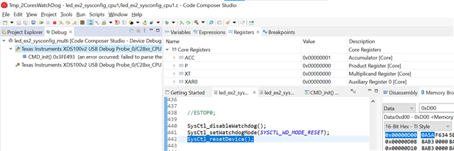
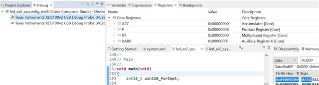
I configured a watchdog for the CPU1: it generates an interrupt, and a reset is asked in its ISR. The main while loop for this CPU executes only a simpel task (led blinking and scalar product), and a call to a "freezing" function. This finction makes the program enter in a infinite loop if the global variable uint16_freeze is set.

I want to test this:

1) I open a debug session

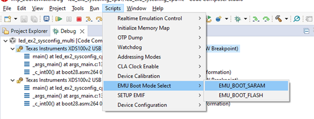
2) I select the right EMU mode for each project:

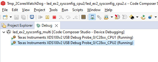
3) I launch the two projects

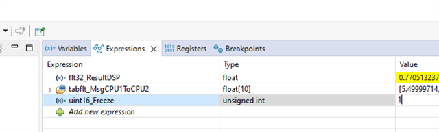
3- I force the freezing of the programm

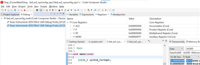
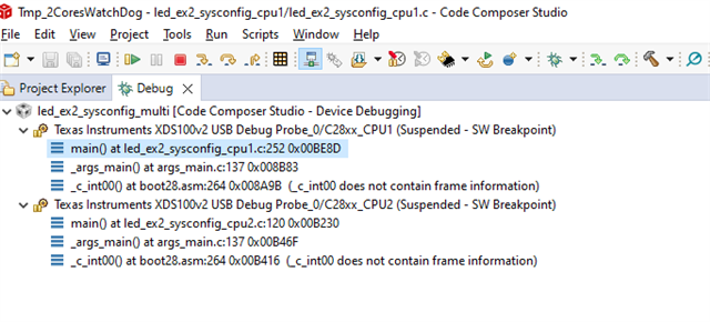
=> The CPU1 is halted because of an error:

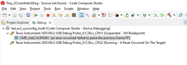
Can somebody tell me what I did wrong ?

thank you

0184.2025_07_04_TISupport.zip

  • Hello,

    To clarify, you are trying to configure emulation boot mode to test your boot flow, correct? 

    Please reference this application note which also walks through the process for emulation boot mode configuration: https://www.ti.com/lit/ug/sprujh3/sprujh3.pdf to verify your process and to see if it helps to resolve your issue.

    Best Regards,

    Allison

  • Hello Allison.

    I knew these informations. My problem is not to make my programm work when I am launching a debug session or whan I am using the micro controller in stand alone mode, but to check that the watchdog works in a debug session for the RAM configuration (so, in a second reset)

    Can you take a look at this issue ?

     TMS320F28379D: Watchdog Management 

    One of your collegue helped me for the FLASH configuration. He asked me to open a new thread for the RAM configuration. So an expert in boot rom could help me.

    Speak you soon

  • Hello Vincent,

    Can you please check the RESC register to confirm the reset cause? Specifically, view the WDRSn bit to see if Watchdog triggered a reset or not.

    The Watchdog reset clears the RAM of this device - is this the intended result? Can you clarify what your expected outcome is? What are your boot pins set to?

    Best Regards,

    Allison

  • Hello Allison.

    If you have a launchpad, maybe you can check that. But down here I try to answer as well as possible.

    Specifically, view the WDRSn bit to see if Watchdog triggered a reset or not.

    I ask for a reset of CPU1 doing this: SysCtl_resetDevice();

    This command should reset both CPU1 and CPU2. Looking in the registers I can see that, when the debug sessions stops: 

    What are your boot pins set to?

    For the FLASH config, since nothing is wrtitten in Zx_BOOT_CTRL registers, the boot is contrilled by default pins, 72 and 84.

    For the RAM config, it is controlled by EMU_BOOT_CTRL, so in the PIE area. When executing the script, 0x0A5A is written at 0x0D00 before the reset.

    You say that the RAM is erased, but after the freeze, I still can read this value in the RAM: 

    Can you make the test on your side ?

    Thank you

  • Hi Vincent,

    You are correct - apologies I misread the watchdog reset does not clear/initialize RAM contents as it is considered a warm reset on this device. 

    I see the EMU key is present. To clarify, can you confirm the registers are being programmed with the correct EMU boot mode as well for both CPUs? What is your EMY_BMODE?

    Best Regards,

    Allison

  • Hello Allison,

    To clarify, can you confirm the registers are being programmed with the correct EMU boot mode as well for both CPUs?

    Yes, I do confirm that:

    What is your EMY_BMODE?

    As you can see, 0x0A (boot at 0x0000, RAM)

    Please, can you run the Archive I sent. I really don't think that this message deals with bootrom flow:

    No source available for "CMD_init() at C:\Users\v.liebart\C2000_Projects\GENERIC\Tmp_2CoresWatchDog\led_ex2_sysconfig_cpu1\RAM\led_ex2_sysconfig_cpu1.out:{3} 0x3fe493{4}" 

  • Hello,

    *Correction*

    As per the F2837xD TRM:

    All RAMs are cleared on WDRSn by the device boot ROM. I've confirmed this is the case with the application archive you provided. 

    No source available for "CMD_init() at C:\Users\v.liebart\C2000_Projects\GENERIC\Tmp_2CoresWatchDog\led_ex2_sysconfig_cpu1\RAM\led_ex2_sysconfig_cpu1.out:{3} 0x3fe493{4}" 

    Address 0x3FE493 is where the ITRAP ISR is located in the boot ROM. Since the application's code start is cleared at 0x0 (M0 RAM) on WD reset, when the device branches to 0x0 in RAM boot with no instructions provided at that address, an ITRAP is hit.

    Best,

    Matt

  • Hello Matt,

    Thank you very much for your explanation.

    It's clear for me.