TMDSCNCD280039C: 280039C LaunchPad the MCAN at CANFD BRS mode, the frame is stufferr.

Part Number: TMDSCNCD280039C
Other Parts Discussed in Thread: C2000WARE

Tool/software:

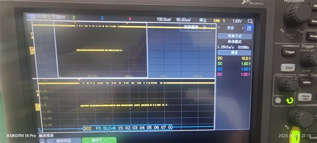
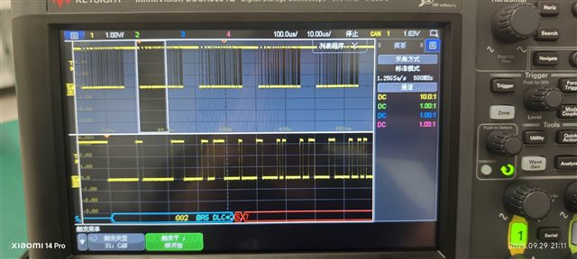
my board is 280039C Launchpad, i use the  MCAN Examples mcan_ex9_transmit   t o test;

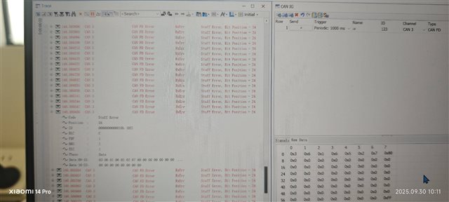
I find that  when i  set  txMsg[loopCnt].brs = 1U;  the canfd stufferr occurred,  if i set the BRS is 0,there is no strufferr,and the data is successfully send;

the versions is  C2000Ware_5_04_00_00;

besides, i build a new project with sysyconfig 1.23, and send message by the cputimer0 ISR, the situation is the same,while i set the txMsg[loopCnt].brs  = 0U; there is no err;

void myMCAN0_init(){
    MCAN_RevisionId revid_myMCAN0;
    MCAN_InitParams initParams_myMCAN0;
    MCAN_ConfigParams configParams_myMCAN0;
    MCAN_MsgRAMConfigParams    msgRAMConfigParams_myMCAN0;
    MCAN_BitTimingParams       bitTimes_myMCAN0;
    //
    // Initialize MCAN Init parameters.
    //
    initParams_myMCAN0.fdMode            = true;
    initParams_myMCAN0.brsEnable         = true;
    initParams_myMCAN0.txpEnable         = false;
    initParams_myMCAN0.efbi              = true;
    initParams_myMCAN0.pxhddisable       = true;
    initParams_myMCAN0.darEnable         = false;
    initParams_myMCAN0.wkupReqEnable     = false;
    initParams_myMCAN0.autoWkupEnable    = false;
    initParams_myMCAN0.emulationEnable   = false;
    initParams_myMCAN0.tdcEnable         = true;
    initParams_myMCAN0.wdcPreload        = 255;
    //
    // Transmitter Delay Compensation parameters.
    //
    initParams_myMCAN0.tdcConfig.tdcf    = 10;
    initParams_myMCAN0.tdcConfig.tdco    = 6;
    //
    // Initialize MCAN Config parameters.
    //
    configParams_myMCAN0.monEnable         = false;
    configParams_myMCAN0.asmEnable         = false;
    configParams_myMCAN0.tsPrescalar       = 15;
    configParams_myMCAN0.tsSelect          = 0;
    configParams_myMCAN0.timeoutSelect     = MCAN_TIMEOUT_SELECT_CONT;
    configParams_myMCAN0.timeoutPreload    = 65535;
    configParams_myMCAN0.timeoutCntEnable  = false;
    configParams_myMCAN0.filterConfig.rrfs = false;
    configParams_myMCAN0.filterConfig.rrfe = false;
    configParams_myMCAN0.filterConfig.anfe = 0;
    configParams_myMCAN0.filterConfig.anfs = 0;
    //
    // Initialize Message RAM Sections Configuration Parameters.
    //
    msgRAMConfigParams_myMCAN0.flssa                = myMCAN0_MCAN_STD_ID_FILT_START_ADDR;
    //
    // Standard ID Filter List Start Address.
    //
    msgRAMConfigParams_myMCAN0.lss                  = myMCAN0_MCAN_STD_ID_FILTER_NUM;
    //
    // List Size: Standard ID.
    //
    msgRAMConfigParams_myMCAN0.flesa                = myMCAN0_MCAN_EXT_ID_FILT_START_ADDR;
    //
    // Extended ID Filter List Start Address.
    //
    msgRAMConfigParams_myMCAN0.lse                  = myMCAN0_MCAN_EXT_ID_FILTER_NUM;
    //
    // List Size: Extended ID.
    //
    msgRAMConfigParams_myMCAN0.txStartAddr          = myMCAN0_MCAN_TX_BUFF_START_ADDR;
    //
    // Tx Buffers Start Address.
    //
    msgRAMConfigParams_myMCAN0.txBufNum             = myMCAN0_MCAN_TX_BUFF_SIZE;
    //
    // Number of Dedicated Transmit Buffers.
    //
    msgRAMConfigParams_myMCAN0.txFIFOSize           = 0;
    msgRAMConfigParams_myMCAN0.txBufMode            = 0;
    msgRAMConfigParams_myMCAN0.txBufElemSize        = 7;
    //
    // Tx Buffer Element Size.
    //
    msgRAMConfigParams_myMCAN0.txEventFIFOStartAddr = myMCAN0_MCAN_TX_EVENT_START_ADDR;
    //
    // Tx Event FIFO Start Address.
    //
    msgRAMConfigParams_myMCAN0.txEventFIFOSize      = myMCAN0_MCAN_TX_EVENT_SIZE;
    //
    // Event FIFO Size.
    //
    msgRAMConfigParams_myMCAN0.txEventFIFOWaterMark = 0;
    //
    // Level for Tx Event FIFO watermark interrupt.
    //
    msgRAMConfigParams_myMCAN0.rxFIFO0startAddr     = myMCAN0_MCAN_FIFO_0_START_ADDR;
    //
    // Rx FIFO0 Start Address.
    //
    msgRAMConfigParams_myMCAN0.rxFIFO0size          = myMCAN0_MCAN_FIFO_0_NUM;
    //
    // Number of Rx FIFO elements.
    //
    msgRAMConfigParams_myMCAN0.rxFIFO0waterMark     = 0; // Rx FIFO0 Watermark.
    msgRAMConfigParams_myMCAN0.rxFIFO0OpMode        = 0;
    msgRAMConfigParams_myMCAN0.rxFIFO1startAddr     = myMCAN0_MCAN_FIFO_1_START_ADDR;
    //
    // Rx FIFO1 Start Address.
    //
    msgRAMConfigParams_myMCAN0.rxFIFO1size          = myMCAN0_MCAN_FIFO_1_NUM;
    //
    // Number of Rx FIFO elements.
    //
    msgRAMConfigParams_myMCAN0.rxFIFO1waterMark     = 0; // Level for Rx FIFO 1
                                                  // watermark interrupt.
    msgRAMConfigParams_myMCAN0.rxFIFO1OpMode        = 0; // FIFO blocking mode.
    msgRAMConfigParams_myMCAN0.rxBufStartAddr       = myMCAN0_MCAN_RX_BUFF_START_ADDR;
    //
    // Rx Buffer Start Address.
    //
    msgRAMConfigParams_myMCAN0.rxBufElemSize        = 7;
    //
    // Rx Buffer Element Size.
    //
    msgRAMConfigParams_myMCAN0.rxFIFO0ElemSize      = 7;
    //
    // Rx FIFO0 Element Size.
    //
    msgRAMConfigParams_myMCAN0.rxFIFO1ElemSize      = 7;
    //
    // Rx FIFO1 Element Size.
    //
    //
    // Initialize bit timings.
    //
    bitTimes_myMCAN0.nomRatePrescalar   = 3; // Nominal Baud Rate Pre-scaler.
    bitTimes_myMCAN0.nomTimeSeg1        = 9; // Nominal Time segment before sample point.
    bitTimes_myMCAN0.nomTimeSeg2        = 8; // Nominal Time segment after sample point.
    bitTimes_myMCAN0.nomSynchJumpWidth  = 7; // Nominal (Re)Synchronization Jump Width Range.
    bitTimes_myMCAN0.dataRatePrescalar  = 1; // Data Baud Rate Pre-scaler.
    bitTimes_myMCAN0.dataTimeSeg1       = 9; // Data Time segment before sample point.
    bitTimes_myMCAN0.dataTimeSeg2       = 8; // Data Time segment after sample point.
    bitTimes_myMCAN0.dataSynchJumpWidth = 7; // Data (Re)Synchronization Jump Width.
    //
    // Get MCANSS Revision ID.
    //
    MCAN_getRevisionId(myMCAN0_BASE, &revid_myMCAN0);
    //
    // Wait for Memory initialization to be completed.
    //
    while(0 == MCAN_isMemInitDone(myMCAN0_BASE));
    //
    // Put MCAN in SW initialization mode.
    //
    MCAN_setOpMode(myMCAN0_BASE, MCAN_OPERATION_MODE_SW_INIT);
    //
    // Wait till MCAN is not initialized.
    //
    while (MCAN_OPERATION_MODE_SW_INIT != MCAN_getOpMode(myMCAN0_BASE));
    //
    // Initialize MCAN module.
    //
    MCAN_init(myMCAN0_BASE, &initParams_myMCAN0);
    //
    // Configure MCAN module.
    //
    MCAN_config(myMCAN0_BASE, &configParams_myMCAN0);
    //
    // Configure Bit timings.
    //
    MCAN_setBitTime(myMCAN0_BASE, &bitTimes_myMCAN0);
    //
    // Configure Message RAM Sections
    //
    MCAN_msgRAMConfig(myMCAN0_BASE, &msgRAMConfigParams_myMCAN0);
    //
    // Internal loopback mode
    //
    MCAN_lpbkModeEnable(myMCAN0_BASE, MCAN_LPBK_MODE_EXTERNAL, false);
    //
    // Take MCAN out of the SW initialization mode
    //
    MCAN_setOpMode(myMCAN0_BASE, MCAN_OPERATION_MODE_NORMAL);
    while (MCAN_OPERATION_MODE_NORMAL != MCAN_getOpMode(myMCAN0_BASE));
}

  • Hi Zhang,

    For the oscilloscope used to capture the MCAN frame, does it have the ability to be configured?  In CAN analyzers, like PeakCAN, there is an option to also set BRS, baud rate (for nominal and data rates), or send ACK bit.  You may also need to set the BRS in the scope so it can distinguish the switching of the bit rates between nominal and data phases.

    Regards,

    Joseph

  • hello, I don't find how to set BRS in my scope, but i did another thing:

    1. I send a CANFD BRS message by my canoe IG,and the CANOE trace shows no err;

    2. I test the message at the CAN transceiver RX Pin and GND, there is no err and can see the BRS at the scope; 

    3. the CANOE and the oscilloscope sample point is 80%,the data rate sample point also is 80%;

    base on the above, i think the oscilloscope and the CANOE is a correct config.

    i want know  if there is something wrong with my  MCAN config ? in ssp, in sjw?

    and i suspect my MCAN message RAM config maybe has wrong, I set the DLC is 8, but the CANOE trace shows the err frame DLC is C;

    can you help me check the message RAM config or the SSP set point or other config?

    below is my message RAM config and some test picture;

    #define myMCAN0_BASE MCANA_DRIVER_BASE
    //
    // Defines
    //
    #define myMCAN0_MCAN_STD_ID_FILTER_NUM          (0)
    #define myMCAN0_MCAN_EXT_ID_FILTER_NUM          (0)
    #define myMCAN0_MCAN_FIFO_0_NUM                 (0)
    #define myMCAN0_MCAN_FIFO_1_NUM                 (0)
    #define myMCAN0_MCAN_TX_BUFF_SIZE               (1)
    #define myMCAN0_MCAN_TX_EVENT_SIZE              (0)
    
    #define myMCAN0_MCAN_STD_ID_FILT_START_ADDR     (0)
    #define myMCAN0_MCAN_EXT_ID_FILT_START_ADDR     (0)
    #define myMCAN0_MCAN_FIFO_0_START_ADDR          (0)
    #define myMCAN0_MCAN_FIFO_1_START_ADDR          (0)
    #define myMCAN0_MCAN_RX_BUFF_START_ADDR         (0)
    #define myMCAN0_MCAN_TX_BUFF_START_ADDR         (0)
    #define myMCAN0_MCAN_TX_EVENT_START_ADDR        (72)
    

  • I have find the incorrect place, the CANOE and the scope sample point both 80%, and arbitration is 500Kbps, the data is 2Mbps,

    but the software config is:

    bitTimes_myMCAN0.nomRatePrescalar = 3; // Nominal Baud Rate Pre-scaler.
    bitTimes_myMCAN0.nomTimeSeg1 = 9; // Nominal Time segment before sample point.
    bitTimes_myMCAN0.nomTimeSeg2 = 8; // Nominal Time segment after sample point.
    bitTimes_myMCAN0.nomSynchJumpWidth = 7; // Nominal (Re)Synchronization Jump Width Range.
    bitTimes_myMCAN0.dataRatePrescalar = 1; // Data Baud Rate Pre-scaler.
    bitTimes_myMCAN0.dataTimeSeg1 = 9; // Data Time segment before sample point.
    bitTimes_myMCAN0.dataTimeSeg2 = 8; // Data Time segment after sample point.
    bitTimes_myMCAN0.dataSynchJumpWidth = 7; // Data (Re)Synchronization Jump Width.

    while i change to the list config, there is no can err;

    bitTimes_myMCAN0.nomRatePrescalar = 3; // Nominal Baud Rate Pre-scaler.
    bitTimes_myMCAN0.nomTimeSeg1 = 14; // Nominal Time segment before sample point.
    bitTimes_myMCAN0.nomTimeSeg2 = 3; // Nominal Time segment after sample point.
    bitTimes_myMCAN0.nomSynchJumpWidth = 3; // Nominal (Re)Synchronization Jump Width Range.
    bitTimes_myMCAN0.dataRatePrescalar = 0; // Data Baud Rate Pre-scaler.
    bitTimes_myMCAN0.dataTimeSeg1 = 14; // Data Time segment before sample point.
    bitTimes_myMCAN0.dataTimeSeg2 = 3; // Data Time segment after sample point.
    bitTimes_myMCAN0.dataSynchJumpWidth = 3; // Data (Re)Synchronization Jump Width.

    so the err is  caused by the wrong  sample point, and the MCAN example project maybe  has unsuitable config;

    another question is that  how to calculate the sample point?

    is

    1- nomTimeSeg2 / (nomTimeSeg2 + 1 + nomTimeSeg1  + 1 + 1)

    or 

    1- (nomTimeSeg2 +1)/ (nomTimeSeg2 + 1 + nomTimeSeg1  + 1 + 1)?

  • Bit rate (nominal or data) is calculated as follows:

         BR = (MCAN Clk/(RatePrescaler + 1))/(TimeSeg1 + TimeSeg2 + 3)

         In the SW example MCAN Clk = 120MHz/(MCLK divider = 3) = 40MHz

    Sampling Point is calculated as:

         SP = (TimeSeg1)/(TimeSeg1 + TimeSeg2)

    The first config parameters are:

         Nom BR = (40MHz/(3+1)) / (9 + 9 + 3) = 500kbps

         Data BR = (40MHz/(1+1)) / (9 + 8 + 3) = 1Mbps

         SP = (9)/(9 + 8) = 53%

    The second config parameters are:

         Nom BR = (40MHz/(3+1)) / (14 + 3 + 3) = 500kbps

         Data BR = (40MHz/(1+0)) / (14 + 3 + 3) = 2Mbps

         SP = (14)/(14 + 3) = 82%

    Obviously, the first config parameter will not work if CANOE is expecting nom rate of 500kbps and data rate of 2Mbps