This thread has been locked.

If you have a related question, please click the "Ask a related question" button in the top right corner. The newly created question will be automatically linked to this question.

TMDSCNCD280039C: MCAN interrupt source setting and trigger.(cannot continue to receive other CanFD commands)

Part Number: TMDSCNCD280039C

Dear Experts,

I am currently trying to use the 280039C to build the functionality of CAN FD.
My idea is to use RF0N (Rx FIFO 0 New Message) to trigger the interrupt, Read RAM FIFO data in interrupt 1.

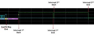
The problem is that when the external CANFD command is issued, there is a successful reception interrupt, but the interrupt is only performed once, and it cannot continue to receive other CanFD commands.

Since the data of the first interrupt can be received, it can be confirmed that my hardware and the interrupt settings have no problem.

Maybe the problem is in some firmware settings or missing some items, I have sorted out some of my basic settings, can you help me determine if there is any problem with my settings?

Overall program as follow

//#############################################################################
//
// FILE:   mcan_ex4_receive.c
//
// TITLE:  MCAN receive using Rx Buffer
//
//! \addtogroup driver_example_c28x_list
//! <h1> MCAN receive using Rx Buffer </h1>
//!
//! This example demonstrates the MCAN receive function. Communication is done
//! between two CAN nodes. The transmitting node could be another MCU or a
//! CAN bus analysis tool capable of transmitting CAN FD frames. The transmit
//! and receive pins of the MCAN module should be connected to a CAN
//! transceiver. Nominal Bit Rate of 500 kbps & Data bit rate of 1 Mbps is used
//!
//! Only Standard frame with message ID 0x4 is received.
//!
//! If another C2000 MCU is used as the transmitter, mcan_ex3_transmit.c can be
//! run on it for the transmit function.
//!
//! \b Hardware \b Required \n
//!  - A C2000 board with CAN transceiver
//!
//! \b External \b Connections \n
//!   Both nodes should communicate through CAN FD capable transceivers.
//!
//!  - MCAN is on DEVICE_GPIO_PIN_CANRXA (MCANRXA)
//!  - and DEVICE_GPIO_PIN_CANTXA (MCANTXA)
//!
//! \b Watch \b Variables \n
//!  - rxMsg
//!
//

//
// Include Files
//
#include "driverlib.h"
#include "device.h"
#include "inc/stw_types.h"
#include "inc/stw_dataTypes.h"
#include <stdint.h>
#include "inc/hw_types_mcan.h"
#include "mcan.h"
#include "debug.h"
#include "interrupt.h"
//
// Defines.
//
#define NUM_OF_MSG                    (1U)
#define MCAN_STD_ID_FILT_START_ADDR     (0x0U)
#define MCAN_STD_ID_FILTER_NUM          (1U)
#define MCAN_EXT_ID_FILT_START_ADDR     (0x14U)
#define MCAN_EXT_ID_FILTER_NUM          (1U)
#define MCAN_TX_BUFF_START_ADDR         (0x80U)
#define MCAN_TX_BUFF_SIZE               (10U)
#define MCAN_FIFO_1_START_ADDR          (0xc0U)
#define MCAN_FIFO_1_NUM                 (10U)
#define MCAN_TX_EVENT_START_ADDR        (0x100U)
#define MCAN_TX_EVENT_SIZE              (10U)
#define MCAN_EXT_ID_AND_MASK            (0x1FFFFFFFU)
#define MCAN_RX_BUFF_START_ADDR         (948U)
#define MCAN_FIFO_0_START_ADDR          (548U)
#define MCAN_FIFO_0_NUM                 (5U)
#define MCAN_MSG_INT                    (0x81200)


#define MCAN0_BASE MCAN_MSG_RAM_BASE
#define INT_MCANSS0 INT_MCAN_0
#define INT_MCANSS1 INT_MCAN_1

//
// Global Variables.
//
volatile uint32_t isrIntr0Flag = 1U;
volatile uint32_t isrIntr1Flag = 1U;
volatile uint16_t monEn = 0x0;
volatile unsigned long msgCount = 0;
int32_t     error = 0;
MCAN_RxBufElement rxMsg[NUM_OF_MSG], rxMsg1;
int32_t loopCnt = 0U;
int16_t UWSeanflag=0;
int16_t UWdataclear=0;
int16_t int0,int1;

//
// Function Prototype.
//
static void MCANConfig(void);
static void MCANIntrConfig(void);
__interrupt void MCANIntr0ISR(void);
__interrupt void MCANIntr1ISR(void);

void main()
{
    int i = 0;
    volatile uint32_t mode = 0U;
    uint32_t dataBytes = 64;
    MCAN_RxNewDataStatus newData;
    newData.statusLow = 0;

    //
    // Initialize device clock and peripherals
    //
    Device_init();

    //
    // Initialize GPIO and unlock the GPIO configuration registers
    //
    Device_initGPIO();

    //
    // Configure the divisor for the MCAN bit-clock
    //
    SysCtl_setMCANClk(SYSCTL_MCANCLK_DIV_2);
    MCANIntrConfig();

    //
    // Configure GPIO pins for MCANTX/MCANRX operation
    //
    GPIO_setPinConfig(DEVICE_GPIO_CFG_MCANRXA);
    GPIO_setPinConfig(DEVICE_GPIO_CFG_MCANTXA);

    //
    // Initialize message to receive
    //
    rxMsg[loopCnt].id = 0U;
    rxMsg[loopCnt].rtr = 0U;
    rxMsg[loopCnt].xtd = 1U;
    rxMsg[loopCnt].esi = 0U;
    rxMsg[loopCnt].rxts = 0U;   // Rx Timestamp
    rxMsg[loopCnt].dlc = 0U;
    rxMsg[loopCnt].brs = 1U;
    rxMsg[loopCnt].fdf = 1U;
    rxMsg[loopCnt].fidx = 0U;   // Filter Index
                                // (of matching Rx acceptance filter element)
    rxMsg[loopCnt].anmf = 0U;   // Accepted Non-matching Frame

    for(i = 0; i < dataBytes; i++)  // Initialize receive buffer to 0
    {
        rxMsg[loopCnt].data[i]  = 0;
    }
    //
    // Configure the MCAN Module.
    //
    MCANConfig();
    //
    // Enable Interrupts.
    //
    MCAN_enableIntr(MCAN0_BASE, MCAN_INTR_MASK_ALL, 1U);
    //MCAN_enableIntr(MCAN0_BASE, MCAN_INTR_SRC_RES_ADDR_ACCESS|
                   //MCAN_INTR_SRC_TIMESTAMP_WRAPAROUND,0);
    //
    // Select Interrupt Line.
    //
    MCAN_selectIntrLine(MCAN0_BASE, MCAN_INTR_MASK_ALL, MCAN_INTR_LINE_NUM_1);

    //
    // Enable Interrupt Line.
    //
    MCAN_enableIntrLine(MCAN0_BASE, MCAN_INTR_LINE_NUM_1, 1U);
    MCAN_getNewDataStatus(MCAN0_BASE, &newData);

}

static void MCANConfig(void)
{
    MCAN_InitParams initParams;
    MCAN_MsgRAMConfigParams    msgRAMConfigParams;
    MCAN_ExtMsgIDFilterElement extFiltelem;
    MCAN_BitTimingParams       bitTimes;

    //
    // Configure MCAN initialization parameters
    //
    initParams.fdMode            = 0x1U; // FD operation enabled.
    initParams.brsEnable         = 0x1U; // Bit rate switching enabled

    //
    // Initialize Message RAM Sections Configuration Parameters
    //
    msgRAMConfigParams.flesa                = MCAN_STD_ID_FILT_START_ADDR;
    msgRAMConfigParams.lse                  = MCAN_STD_ID_FILTER_NUM;
    msgRAMConfigParams.flesa                = MCAN_EXT_ID_FILT_START_ADDR;
    msgRAMConfigParams.lse                  = MCAN_EXT_ID_FILTER_NUM;
    msgRAMConfigParams.txStartAddr          = MCAN_TX_BUFF_START_ADDR;
    msgRAMConfigParams.txBufNum             = MCAN_TX_BUFF_SIZE;
    msgRAMConfigParams.txFIFOSize           = 0U;
    msgRAMConfigParams.txBufMode            = 0U;
    msgRAMConfigParams.txBufElemSize        = MCAN_ELEM_SIZE_64BYTES;
    msgRAMConfigParams.txEventFIFOStartAddr = MCAN_TX_EVENT_START_ADDR;
    msgRAMConfigParams.txEventFIFOSize      = MCAN_TX_BUFF_SIZE;
    msgRAMConfigParams.txEventFIFOWaterMark = 3U;
    msgRAMConfigParams.rxFIFO0startAddr     = MCAN_FIFO_0_START_ADDR;
    msgRAMConfigParams.rxFIFO0size          = MCAN_FIFO_0_NUM;
    msgRAMConfigParams.rxFIFO0waterMark     = 3U;
    msgRAMConfigParams.rxFIFO0OpMode        = 0U;
    msgRAMConfigParams.rxFIFO1startAddr     = MCAN_FIFO_1_START_ADDR;
    msgRAMConfigParams.rxFIFO1size          = MCAN_FIFO_1_NUM;
    msgRAMConfigParams.rxFIFO1waterMark     = 3U;
    msgRAMConfigParams.rxFIFO1OpMode        = 0U;
    msgRAMConfigParams.rxBufStartAddr       = MCAN_RX_BUFF_START_ADDR;
    msgRAMConfigParams.rxBufElemSize        = MCAN_ELEM_SIZE_64BYTES;
    msgRAMConfigParams.rxFIFO0ElemSize      = MCAN_ELEM_SIZE_64BYTES;
    msgRAMConfigParams.rxFIFO1ElemSize      = MCAN_ELEM_SIZE_64BYTES;

    extFiltelem.efid1 = 0x18EFB324U;
    extFiltelem.eft   = 0x1U;
    extFiltelem.efec  = 0x1U;
    //
    // Initialize bit timings.
    //
    bitTimes.nomRatePrescalar   = 0x7U; // Nominal Baud Rate Pre-scaler
    bitTimes.nomTimeSeg1        = 0x9U; // Nominal Time segment before SP
    bitTimes.nomTimeSeg2        = 0x3U; // Nominal Time segment after SP
    bitTimes.nomSynchJumpWidth  = 0x4U; // Nominal SJW
    bitTimes.dataRatePrescalar  = 0x0U; // Data Baud Rate Pre-scaler
    bitTimes.dataTimeSeg1       = 0x9U; // Data Time segment before SP
    bitTimes.dataTimeSeg2       = 0x0U; // Data Time segment after SP
    bitTimes.dataSynchJumpWidth = 0x4U; // Data SJW

    //
    // Wait for memory initialization to happen.
    //
    while(FALSE == MCAN_isMemInitDone(MCAN0_BASE))
    {
    }

    //
    // Put MCAN in SW initialization mode.
    //
    MCAN_setOpMode(MCAN0_BASE, MCAN_OPERATION_MODE_SW_INIT);

    //
    // Wait till MCAN is not initialized.
    //
    while (MCAN_OPERATION_MODE_SW_INIT != MCAN_getOpMode(MCAN0_BASE))
    {}

    //
    // Initialize MCAN module.
    //
    MCAN_init(MCAN0_BASE, &initParams);

    //
    // Configure Bit timings.
    //
    MCAN_setBitTime(MCAN0_BASE, &bitTimes);

    //
    // Configure Message RAM Sections
    //
    MCAN_msgRAMConfig(MCAN0_BASE, &msgRAMConfigParams);

    //
    // Configure Standard ID filter element
    //
    //MCAN_addStdMsgIDFilter(MCAN0_BASE, 0U, &stdFiltelem);
    MCAN_addExtMsgIDFilter(MCAN0_BASE, 0U, &extFiltelem);

    //
    // Take MCAN out of the SW initialization mode
    //
    MCAN_setOpMode(MCAN0_BASE, MCAN_OPERATION_MODE_NORMAL);

    while (MCAN_OPERATION_MODE_NORMAL != MCAN_getOpMode(MCAN0_BASE))
    {

    }
}
static void MCANIntrConfig(void)
{

    Interrupt_initModule();
    Interrupt_initVectorTable();
    Interrupt_register(INT_MCANSS0,&MCANIntr0ISR);
    Interrupt_enable(INT_MCANSS0);
    Interrupt_register(INT_MCANSS1,&MCANIntr1ISR);
    Interrupt_enable(INT_MCANSS1);
    Interrupt_enableMaster();

}

//
// This is Interrupt Service Routine for MCAN interrupt 0.
//
__interrupt void MCANIntr0ISR(void)
{
    uint32_t intrStatus;
    intrStatus = MCAN_getIntrStatus(MCAN0_BASE);
    int0++;
    if (MCAN_MSG_INT != intrStatus)
    {
        error++;
    }

    //
    // Clear the interrupt Status.
    //
    MCAN_clearIntrStatus(MCAN0_BASE, intrStatus);

    //
    // Update the flag value.
    //
    isrIntr0Flag = 0U;

    //
    // Acknowledge this interrupt located in group 9
    //
    Interrupt_clearACKGroup(INTERRUPT_ACK_GROUP9);
}

//
// This is Interrupt Service Routine for MCAN interrupt 1.
//
__interrupt void MCANIntr1ISR(void)
{
    uint32_t intrStatus;
    int1++;
    MCAN_RxNewDataStatus newData;
    intrStatus = MCAN_getIntrStatus(MCAN0_BASE);
    if (MCAN_MSG_INT != intrStatus)
    {
        error++;
    }
    MCAN_getNewDataStatus(MCAN0_BASE, &newData);
    MCAN_readMsgRam(MCAN0_BASE, MCAN_MEM_TYPE_FIFO, 0, MCAN_RX_FIFO_NUM_0, &rxMsg1);
    rxMsg[loopCnt] = rxMsg1;
    MCAN_writeRxFIFOAck(MCAN0_BASE, MCAN_RX_FIFO_NUM_0, 0);
    MCAN_clearNewDataStatus(MCAN0_BASE, &newData);
    //
    // Clear the interrupt Status.
    //
    HW_WR_FIELD32(MCAN0_BASE + MCAN_MCANSS_EOI, MCAN_MCANSS_EOI, 0x1U);
    MCAN_clearIntrStatus(MCAN0_BASE, intrStatus);

    //
    // Update the flag value.
    //
    isrIntr1Flag = 0U;

    //
    // Acknowledge this interrupt located in group 9
    //
    Interrupt_clearACKGroup(INTERRUPT_ACK_GROUP9);
}

line 150 : Setting the enable interrupts source

line 156 : Select Interrupt MCAN interrupt 1.

line 161 : Enable Interrupt MCAN interrupt 1.

line 207 & line 208 & line 209 : Set the filter for ID and store the message in FIFO0.

line 327 : Read received message form message RAM.

line 328 : Copy messages from RAM to custom array.

line 329 : write Rx FIFO Acknowledgement.

line 335 :clear the interrupt status.

Thanks for your help!!

  • Sean, 

    Your query is being reviewed and we will get back to you shortly.

    Thanks.

  • Sean, 

    Looking at line 150

        //
        // Enable Interrupts.
        //
        MCAN_enableIntr(MCAN0_BASE, MCAN_INTR_MASK_ALL, 1U);      <<<<<<<<--------

    While setting the interrupt source, you have selected MCAN_INTR_MASK_ALL, which means all possible interrupt sources will result in the ISR being called. Your issue, according to me, is probably being caused by the ISR being called due to some other interrupt source when new data has not been received yet. 

    Replacing the line as below:

        //
        // Enable Interrupts.
        //
        MCAN_enableIntr(MCAN0_BASE, MCAN_IR_RF0N_MASK, 1U);

    Now the source of the interrupt will only be when a new message is written to Rx FIFO 0 which was your intent.

    My idea is to use RF0N

    Please try the same and let me know.

    Thanks.

  • Hi Sahil,

    Thanks for your reply, I really didn't consider the problem caused by other interrupt sources.

    After the adjustment, I can receive messages normally. But here comes the second problem, I adjusted the code as follows:

    //
    // Include Files
    //
    #include "driverlib.h"
    #include "device.h"
    #include "inc/stw_types.h"
    #include "inc/stw_dataTypes.h"
    #include <stdint.h>
    #include "inc/hw_types_mcan.h"
    #include "mcan.h"
    #include "debug.h"
    #include "interrupt.h"
    //
    // Defines.
    //
    #define NUM_OF_MSG                    (1U)
    #define MCAN_EXT_ID_FILT_START_ADDR     (0x14U)
    #define MCAN_EXT_ID_FILTER_NUM          (1U)
    #define MCAN_RX_BUFF_START_ADDR         (948U)
    #define MCAN_MSG_INT                    (0x81200)
    #define MCAN0_BASE MCAN_MSG_RAM_BASE
    #define INT_MCANSS1 INT_MCAN_1
    
    //
    // Global Variables.
    
    volatile uint32_t isrIntr1Flag = 1U;
    volatile unsigned long msgCount = 0;
    int32_t     error = 0;
    int32_t loopCnt = 0U;
    int16_t int1;
    //
    // Function Prototype.
    //
    static void MCANConfig(void);
    static void MCANIntrConfig(void);
    __interrupt void MCANIntr1ISR(void);
    
    MCAN_RxBufElement rxMsg[NUM_OF_MSG], rxMsg1;
    MCAN_RxFIFOStatus    RxFS;
    MCAN_RxNewDataStatus newData;
    void main()
    {
        int i = 0;
        volatile uint32_t mode = 0U;
        uint32_t dataBytes = 64;
        newData.statusLow = 0;
    
        //
        // Initialize device clock and peripherals
        //
        Device_init();
    
        //
        // Initialize GPIO and unlock the GPIO configuration registers
        //
        Device_initGPIO();
    
        //
        // Configure the divisor for the MCAN bit-clock
        //
        SysCtl_setMCANClk(SYSCTL_MCANCLK_DIV_1);
        MCANIntrConfig();
    
        //
        // Configure GPIO pins for MCANTX/MCANRX operation
        //
        GPIO_setPinConfig(DEVICE_GPIO_CFG_MCANRXA);
        GPIO_setPinConfig(DEVICE_GPIO_CFG_MCANTXA);
        GPIO_setPinConfig(DEVICE_GPIO_CFG_Test1);
        GPIO_setDirectionMode(DEVICE_GPIO_PIN_Test1, GPIO_DIR_MODE_OUT);
    
        //
        // Initialize message to receive
        //
        rxMsg[loopCnt].id = 0U;
        rxMsg[loopCnt].rtr = 0U;
        rxMsg[loopCnt].xtd = 1U;
        rxMsg[loopCnt].esi = 0U;
        rxMsg[loopCnt].rxts = 0U;   // Rx Timestamp
        rxMsg[loopCnt].dlc = 0U;
        rxMsg[loopCnt].brs = 1U;
        rxMsg[loopCnt].fdf = 1U;
        rxMsg[loopCnt].fidx = 0U;   // Filter Index
                                    // (of matching Rx acceptance filter element)
        rxMsg[loopCnt].anmf = 0U;   // Accepted Non-matching Frame
    
        for(i = 0; i < dataBytes; i++)  // Initialize receive buffer to 0
        {
            rxMsg[loopCnt].data[i]  = 0;
        }
        //
        // Configure the MCAN Module.
        //
        MCANConfig();
        //
        //
        // Enable Interrupts.
        //
        MCAN_enableIntr(MCAN0_BASE, MCAN_INTR_MASK_ALL, 0U);
        MCAN_enableIntr(MCAN0_BASE, MCAN_IR_DRX_MASK, 1U);
        // Select Interrupt Line.
        MCAN_selectIntrLine(MCAN0_BASE, MCAN_IR_DRX_MASK, MCAN_INTR_LINE_NUM_1);
        //
        // Enable Interrupt Line.
        //
        MCAN_enableIntrLine(MCAN0_BASE, MCAN_INTR_LINE_NUM_1, 1U);
        MCAN_getNewDataStatus(MCAN0_BASE, &newData);
    
    }
    
    static void MCANConfig(void)
    {
        MCAN_InitParams initParams;
        MCAN_MsgRAMConfigParams    msgRAMConfigParams;
        MCAN_ExtMsgIDFilterElement extFiltelem;
        MCAN_BitTimingParams       bitTimes;
    
        //
        // Configure MCAN initialization parameters
        //
        msgRAMConfigParams.flesa                = MCAN_EXT_ID_FILT_START_ADDR;
        msgRAMConfigParams.lse                  = MCAN_EXT_ID_FILTER_NUM;
        initParams.fdMode            = 0x1U; // FD operation enabled.
        initParams.brsEnable         = 0x1U; // Bit rate switching enabled
    
        //
        // Initialize Message RAM Sections Configuration Parameters
        //
    
        msgRAMConfigParams.rxBufStartAddr       = MCAN_RX_BUFF_START_ADDR;
        msgRAMConfigParams.rxBufElemSize        = MCAN_ELEM_SIZE_64BYTES;
    
        extFiltelem.efid2 = 0U;
        extFiltelem.efid1 = 0x18EFB324U;
        extFiltelem.eft   = 0x1U;
        extFiltelem.efec  = 0x7U;
        //
        // Initialize bit timings.
        //
        bitTimes.nomRatePrescalar   = 0x2U; // Nominal Baud Rate Pre-scaler
        bitTimes.nomTimeSeg1        = 0x3AU; // Nominal Time segment before SP
        bitTimes.nomTimeSeg2        = 0x13U; // Nominal Time segment after SP
        bitTimes.nomSynchJumpWidth  = 0x4U; // Nominal SJW
        bitTimes.dataRatePrescalar  = 0x2U; // Data Baud Rate Pre-scaler
        bitTimes.dataTimeSeg1       = 0x4U; // Data Time segment before SP
        bitTimes.dataTimeSeg2       = 0x1U; // Data Time segment after SP
        bitTimes.dataSynchJumpWidth = 0x4U; // Data SJW
    
        //
        // Put MCAN in SW initialization mode.
        //
        MCAN_setOpMode(MCAN0_BASE, MCAN_OPERATION_MODE_SW_INIT);
    
        //
        // Wait till MCAN is not initialized.
        //
        while (MCAN_OPERATION_MODE_SW_INIT != MCAN_getOpMode(MCAN0_BASE))
        {}
    
        //
        // Initialize MCAN module.
        //
        MCAN_init(MCAN0_BASE, &initParams);
    
        //
        // Configure Bit timings.
        //
        MCAN_setBitTime(MCAN0_BASE, &bitTimes);
    
        //
        // Configure Message RAM Sections
        //
        MCAN_msgRAMConfig(MCAN0_BASE, &msgRAMConfigParams);
    
        //
        // Configure Standard ID filter element
        //
        MCAN_addExtMsgIDFilter(MCAN0_BASE, 0U, &extFiltelem);
    
        //
        // Take MCAN out of the SW initialization mode
        //
        MCAN_setOpMode(MCAN0_BASE, MCAN_OPERATION_MODE_NORMAL);
    
    }
    static void MCANIntrConfig(void)
    {
    
        Interrupt_initModule();
        Interrupt_initVectorTable();
        Interrupt_register(INT_MCANSS1,&MCANIntr1ISR);
        Interrupt_enable(INT_MCANSS1);
        Interrupt_enableMaster();
    
    }
    
    //
    // This is Interrupt Service Routine for MCAN interrupt 1.
    //
    __interrupt void MCANIntr1ISR(void)
    {
        GPIO_writePin(40,1);
        uint32_t intrStatus;
        int1++;
        intrStatus = MCAN_getIntrStatus(MCAN0_BASE);
        MCAN_getNewDataStatus(MCAN0_BASE, &newData);
        MCAN_readMsgRam(MCAN0_BASE, MCAN_MEM_TYPE_BUF, 0, 0, &rxMsg1);
        rxMsg[loopCnt] = rxMsg1;
        MCAN_clearNewDataStatus(MCAN0_BASE, &newData);
        HW_WR_FIELD32(MCAN0_BASE + MCAN_MCANSS_EOI, MCAN_MCANSS_EOI, 0x2U);
        MCAN_clearIntrStatus(MCAN0_BASE, intrStatus);
    
        //
        // Update the flag value.
        //
        isrIntr1Flag = 0U;
    
        //
        // Acknowledge this interrupt located in group 9
        //
        Interrupt_clearACKGroup(INTERRUPT_ACK_GROUP9);
        GPIO_writePin(40,0);
    }
    

    line 154 to 157 : Setting the enable interrupts source MCAN_IR_RF0N_MASK only.

    line  318 & 347 : Digital output Setting.

    line 320 : Interrupt counter.

    I found that when I received a message, It would enter twice interrupt, and my expectation was to enter only once interrupt.

    Then I use the digital output to watch the CANFD signal and when the interrupt comes in. Indeed, it interrupts twice after receiving the message.

    I have blocked other interrupt sources (line154), is there any other reason for this?

    Thank you very much!!

  • Sean, 

    Your query is being reviewed and we will get back to you shortly.

    Thanks.

  • Hi Sahil,

    Any suggestion on this topic? Thank you for your help!

  • Sean,

    Can you please help me understand on how many packets are you transferring, it is not very clear from the waveform you had attached?

    Also, can you let us know what is the 'intrStatus' variable status each time you are hitting the ISR(to understand the source of the interrupt)?

    Regards,

    Praveen