This thread has been locked.

If you have a related question, please click the "Ask a related question" button in the top right corner. The newly created question will be automatically linked to this question.

TMS320F28377D: Unexpected PC address and LCR behavior at low tempture

Part Number: TMS320F28377D

Hi Experts,

My customer seeing unexpected behaviour of CPU2 when doing low temperature tests. 

  1. Put the board into -15 degree enviorment. Wait for ~ 10 minutes
  2. Take the board to room temperature, and power the board.
  3. There is two LED as incidators for two CPUs, LED1 for CPU1, LED2 for CPU2. LED1 is blinking, and LED2 is not, which means CPU2 is not running normally.
  4. Connect to emulator with GEL file removed.
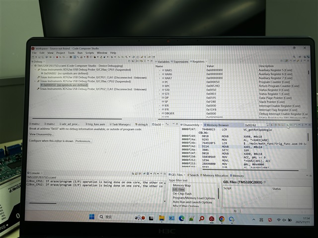
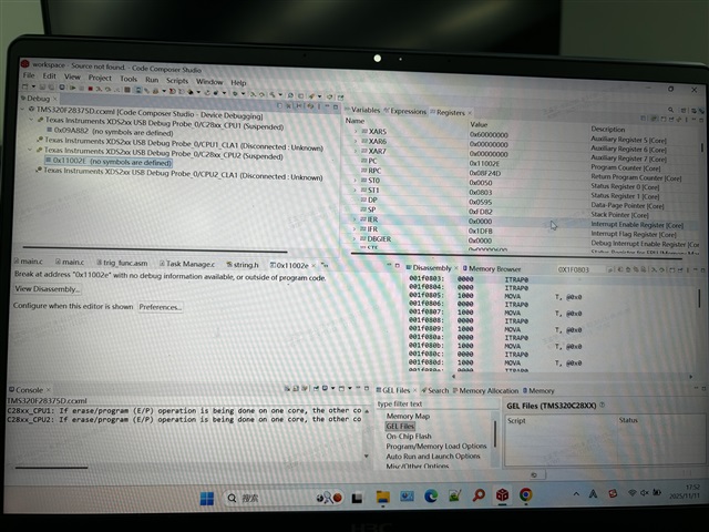
  5. CPU1 is running in normal memory spaces, the PC of CPU2 is on external memory spaces (Picture 1) at this point, for CPU2 PC = 0x11002E, RPC =0x8F24D, SP=0xFD82(origin = 0x400, size = 0x3f0)
  6. I would like to trace back where CPU2 is branching to unexpected location, so I set the PC to RPC-2 = 0x8f24b, which is a LCR instruction, and step through the code.
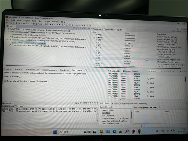
  7. I see this LCR instruction is executed incorrectly (Picture 2), from the OP code, it should branch to 0x928f5, which aligns with the symbol, however, upon executing this instruction, the CPU2 branch to 0x50 instead ()
  8. I use the "move to" function to execute this LCR instrcution for a couple of times, the result are the same. 

Could you please help providing insights on why this is happening.

Note that this only happens at low temperature, and it occurs on two boards (returned from end user) only for now.

 

  • Hello Hang,

    Thank you for reporting this issue. To help us better understand and troubleshoot the problem, I notice some missing information that would be helpful:

    Images:
    - You mentioned two pictures in your post, but they appear to be missing. Could you please attach them?

    Test Environment Details:
    1. Hardware Setup
    - What EVM/hardware platform are you using?
    - Please provide the complete system configuration/expectations used during testing
    - Board initialization procedure before beginning temp testing

    2. Temperature Testing
    - Is this -15° Fahrenheit or Celsius?
    - What method/equipment are you using for temperature control?
    - Have you verified if this issue:
    * Only occurs at low temperature?
    * Can be reproduced at room temperature (~25°C)?
    * Occurs at elevated temperatures?
    - Duration of temperature exposure before testing (if this is shortened to 2 minutes or 5 minutes does the problem persist?)

    3. Test Procedure
    - Could you provide a detailed breakdown of Step 4 in your procedure?
    - What is the exact sequence of operations?
    - Are there any observable symptoms before the failure occurs?

    Once you provide these details, we'll be better equipped to assist you in resolving this issue.

    Best regards,
    Zackary Fleenor

  • Hi Fleenor,

    Adding the missing pictures.

    Picture 1

    Picture 2

    Picture 3

  • Hi Fleenor,

    Adding the missing pictures.

    Picture 1

    Picture 2

    Picture 3

  • Test Environment Details:
    1. Hardware Setup
    - What EVM/hardware platform are you using? Custom board
    - Please provide the complete system configuration/expectations used during testing -> The board is running custom application
    - Board initialization procedure before beginning temp testing -> There is no initialization at all. The board is being hold in the low temperature chamber, without connection, without power. We only power and connect to the board after taking it out of the chamber

    2. Temperature Testing
    - Is this -15° Fahrenheit or Celsius? -> Yes
    - What method/equipment are you using for temperature control? -> a refrigerator
    - Have you verified if this issue:
    * Only occurs at low temperature? -> Yes, this would not occurs at room temperature 
    * Can be reproduced at room temperature (~25°C)? -> No, to clarify more, this is reproduced on a board just come out from a low temperature environment, but by the time we power the board, it's at room temperature. You may consider that the board is cold, but the environment is room temperature. In order to reproduce it, we need to power the board soon, otherwise the board will warm up and the issue can not be reproduced.
    * Occurs at elevated temperatures? -> We only tested -15 Celsius
    - Duration of temperature exposure before testing (if this is shortened to 2 minutes or 5 minutes does the problem persist?) -> We didn't try variation in the exposure time. But the problem would not occur if we don't expose it to low temperature at all.

    3. Test Procedure
    - Could you provide a detailed breakdown of Step 4 in your procedure?-> Launch target configuration -> Click CPU1 -> remove GEL file -> Click CPU2 -> remove GEL file -> connect CPU1 -> connect CPU2 
    - What is the exact sequence of operations? -> take the board out from the refrigerator -> power the board -> connect to both CPU like above -> take picture -> mark RPC. calculate RPC-2 value, enter the value in the disassembly window -> Find the corresponding line in the disassembly window, right click and move to (Which is the LCR) -> take picture 2-> click assembly step into -> take picture 3. 
    - Are there any observable symptoms before the failure occurs? -> Since we only power the board after taken it out from the refrigerator, there is nothing much to see before we power the board, as soon as we power the board, we can tell from immediately from the LED the failure occurs

  • Hi Hang,

    Thank you for providing the pictures and additional details. This information helps.

    One thing to try,

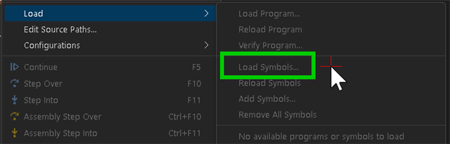
    After connecting to the CPUs, Use the Load -> Load Symbols function before continuing.

    What is the setup/configuration steps done at power on for the custom application?

    Is the code already loaded to flash and set to boot from flash on power up?

    Does the code load occur before or after the refrigeration process?

    If you instead connect via JTAG and load/execute the code directly from RAM, does the issue persist?

    Best Regards,

    Zackary Fleenor

  • We've loaded the symbols in earlier test, sorry for missing that in desciprtino, but you can see in the pictures that the symbol are there.

    What is the setup/configuration steps done at power on for the custom application? -> Is there any specific item you are looking for? There are a lot the configuration on the system/peripherals since it's an actual application. 

    Is the code already loaded to flash and set to boot from flash on power up? Yes, the code is flashed to the device before refrigeration, and it's there all the time.

    If you instead connect via JTAG and load/execute the code directly from RAM, does the issue persist? We didn't test this, but we do try reset and restart the device, and the issue would not occur. It only occurs at power on.

  • Adding more update.

    1. I tested using the example code on custom board today. However, I cannot reproduce the issue with the dual LED example.

    2. As said in above, the board is in some kink of "error state" after taken out from the refrigerator. In this state, the CPU seems to be executing instruction incorrectly. As said in above, the LCR instruction is branching unexepcted location. I tried more instruction by using the "move to" function, for example, I move to the beginning of the main, and execute the first instruction, which is a MOVL, but the CPU behaves like branching, as shown in the video

    3. The next thing I tried is loading the dual example code to the board in error state (note that this is different from #1, where the example code is loaded before putting the board in refrigerator) I find the LED of the two CPU is blinking, which means CPU1 and CPU2 are exedcuting instructions correctly, however, the speed of the blink is much slower than normal. Next I checked the clocking registers, Seems the clock is abnormal (for example, PLL is not locked)

    4. I tried to locate the place where CPU2 begins to behave unexpectedly, the way I do it is adding a global variable in the CPU2 code, this variable x is assigned to different values at different stage of the code, like a checkpoint. I read the value of this variable x when the board comes out from the refrigerator. Turns out that the code is executed correctly until it runs to a particular ISR 


  • Hi Zack,

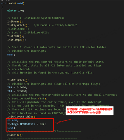
    In the meantime, could you please help confirming the BOOTSTS register in below picture is set by CPU2 boot rom, and user is not required to set it? More information on where this register is set (like which boot mode/which step.)are well appreciated!


    For the record, we are not seeing IPC issues in board we are testing!

    They claim that there is a IPC issue before but later I find it's not an IPC issue, I am just getting feedback as they require. This IPC issue might not relate to the issue we are seeing now

  • Hi Hang,

    Additional details can be found in the 2.1.4 CPU2 Boot Flow section of the document below:

    https://www.ti.com/lit/ug/sprujh3/sprujh3.pdf

    Note the details described in the two E2E threads below.

     TMS320F28379D: CPU2 boot status signalling to CPU1 (IPCBOOTSTS) 

     F2837xD booting both CPUs from Flash 

    As mentioned by Michael Rindsig,

    "My company can't have different builds for emulator/non-emulator modes, so we ended up adding this line at the very beginning of Core2 main code (right after InitSysCtrl()):

    IpcRegs.IPCBOOTSTS = C2_BOOTROM_BOOTSTS_SYSTEM_READY;

    That will prevent a stall in emulation mode, and in non-emulation mode the value of this register has already been set to C2_BOOTROM_BOOTSTS_C2TOC1_BOOT_CMD_ACK at this point and the register is no longer used."

    I would follow this suggestion and move the manual configuration of IPCBOOTSTS to follow the InitSysCtrl() function and before the remaining Init functions.

    Best Regards,

    Zackary Fleenor