This thread has been locked.

If you have a related question, please click the "Ask a related question" button in the top right corner. The newly created question will be automatically linked to this question.

TMS320F280039: HWBIST and interrupt

Part Number: TMS320F280039
Other Parts Discussed in Thread: LAUNCHXL-F280039C

Background Introduction:
1)The system uses interrupt sources including DMA_CH1/DCANA_0/DCANA_1/TIMER2.
2)DMA_CH1 is a 50µs control interrupt; TIMER2 is a 1ms OS interrupt; DCANA_0 is a CAN error and status interrupt; DCANA_1 is a CAN mailbox communication interrupt.
3)The underlying layer is configured and generated using SysCfg, employing an interrupt nesting scheme. The interrupt nesting priority follows the default TI priority settings without any modifications.
4)The product must comply with IEC60730 Class B requirements, therefore HWBIST-related code must be added.

Issues:
1)STL_HWBIST_runMicro() is called within the control interrupt (50µs).
2)When performing HWBIST detection, a spurious interrupt for TIMER2 is triggered. Referring to the forum issue: tms320f280025-spurious-interrupts-after-hwbist-test. The TIMER2 ISR was modified as follows: clear the TIMER2 TIF bit immediately upon entering the TIMER2 interrupt handler. After this change, TIMER2 enters normally every 1ms.
3)After running for some time, it was observed that the control interrupt (DMA_CH1) and OS interrupt (TIMER2) can both enter normally, but the CAN1 interrupt cannot enter. If STL_HWBIST_runMicro() is disabled in the control interrupt, the issue of CAN1 interrupt not entering does not occur.

  • Can you tell if it's specifically happening when the CAN interrupt is triggered during the HWBIST? Can you see the CAN interrupt flags getting set in the registers (both in the CAN and in the PIE)?

    Whitney

  • During HWBIST micro testing, it is not convenient to connect a debugger. Therefore, observing related registers/variables during testing is not very convenient for me.

    1) Below is 50us DMA control ISR code for test.

    __interrupt void INT_BswDma_DMA1_ADCACH0_6_ISR(void)
    {
        //
        // Save IER register on stack
        //
        volatile uint16_t tempPIEIER = HWREGH(PIECTRL_BASE + PIE_O_IER7);
    
        //
        // Set the global and group priority to allow CPU interrupts
        // with higher priority
        //
        IER |= M_INT7;
        IER &= MINT7;
        HWREGH(PIECTRL_BASE + PIE_O_IER7) &= MG7_1;
    
        //
        // Enable Interrupts
        //
        Interrupt_clearACKGroup(0xFFFFU);
        __asm("  NOP");
        EINT;
    
        //
        // Insert ISR Code here ..
        //
        GvUtility_TestData_U[0].u32data++;
        STL_HWBIST_runMicro();
    
        //
        // Disable interrupts and restore registers saved:
        //
        DINT;
        HWREGH(PIECTRL_BASE + PIE_O_IER7) = tempPIEIER;
    }

    2)Below is the CAN receive interrupt ISR Code.

    __interrupt void INT_BswCan_CANA_1_ISR(void)
    {
        //
        // Save IER register on stack
        //
        volatile uint16_t tempPIEIER = HWREGH(PIECTRL_BASE + PIE_O_IER9);
    
        //
        // Set the global and group priority to allow CPU interrupts
        // with higher priority
        //
        IER |= M_INT9;
        IER &= MINT9;
        HWREGH(PIECTRL_BASE + PIE_O_IER9) &= MG9_6;
    
        //
        // Enable Interrupts
        //
        Interrupt_clearACKGroup(0xFFFFU);
        __asm("  NOP");
        EINT;
    
        //
        // Insert ISR Code here ..
        //
    
        BswCan_MsgCallback();
    
        //
        // Disable interrupts and restore registers saved:
        //
        DINT;
        HWREGH(PIECTRL_BASE + PIE_O_IER9) = tempPIEIER;
    
        #ifdef TRACE_ISR_ENABLE
            //
            //  Add ISR to Trace
            //
            traceISR[traceISRIndex % TRACE_SIZE] = 0x0906;
            traceISRIndex++;
        #endif
    }

    3)I have done some tests as follows:

    When a CAN communication exception occurs, PIE_IER9 is normal, but PIE_IFR9 is continuously set. I suspect this may be related to the CPU-level IER register.

  • Thanks for your patience. Have you been able to do any additional debugging? I know HWBIST can make debugging challenging. Do you have some IOs that you could toggle in your ISRs or before and after running HWBIST to try to figure out the behavior seems to be related to interrupt nesting or if it specifically happens when an interrupt occurs during the HWBIST micro run? That could give us some hints about what may be happening.

    I don't see anything concerning in your ISRs. I'm thinking about your comment--"PIE_IER9 is normal, but PIE_IFR9 is continuously set." PIEIFR9 being set but the interrupt not being triggered could either be caused by an issue of the PIEACK not being reset after the last group 9 interrupt or either the CPU IER or INTM not be enabled. PIEIFR is supposed to get cleared when the CPU fetches the ISR vector from the PIE.

    Whitney

  • I apologize for the delayed response due to the Chinese Spring Festival holiday.

    The following are the further tests I have conducted so far:
    1)When calling the function STL_HWBIST_runMicro within a 1ms task, the issue of being unable to enter the CAN interrupt was not reproduced.
    2)When calling the function STL_HWBIST_runMicro within a 20kHz control interrupt, the issue of being unable to enter the CAN interrupt occurs.
    3)Based on test 2, I attempted to clear the ACK flag using Interrupt_clearACKGroup(INTERRUPT_ACK_GROUP9). This allowed re-entry into the CAN interrupt, but after running for a while, the issue reappeared.
    4)Based on test 2, I attempted to enable the IER using Interrupt_enable(INT_CANA1), but it had no effect, and the issue of being unable to enter the CAN interrupt could not be resolved.

    Additional questions:
    1)Our product application is a bidirectional DC converter that needs to meet IEC60730 Class B requirements. Would you recommend calling the function STL_HWBIST_runMicro within a 20kHz control interrupt, or within a background slow task (1ms/10ms)?
    2)Does the function STL_HWBIST_runMicro need to be called continuously, or can it be stopped once the coverage test is complete and it returns STL_HWBIST_BIST_DONE?

  • Could you tell me if there is any new information on this issue?

  • . Would you recommend calling the function STL_HWBIST_runMicro within a 20kHz control interrupt, or within a background slow task (1ms/10ms)?

    I'm not sure if the standard has a particular requirement for this or if you need to decide for your own system. Do you have a requirement of how frequently your full set of tests need to be repeated? Recall the STl_HWBIST_runMicro is doing a single micro run and that it needs to be run 750 times to reach its maximum amount of diagnostic coverage.

    2)Does the function STL_HWBIST_runMicro need to be called continuously, or can it be stopped once the coverage test is complete and it returns STL_HWBIST_BIST_DONE?

    I think you'd want to run it continuously normally--meaning run it until it returns STL_HWBIST_BIST_DONE, reinitialize it, and repeat. However, class B requirements for CPU testing don't necessarily need HWBIST. We have devices without HWBIST that meet the class B requirements by performing a software test of the CPU registers using the SDL's STL_CPU_REG module and an additional PC counter test, so you could consider doing that as a periodic test instead of HWBIST.

    Whitney

  • 1.We are using a closed-loop control system, and I believe it would be better to perform the call during the high-speed control interrupt for the following reasons:
    1.1)It enables faster fault diagnosis.
    1.2)Since HWBIST requires suspending interrupt execution, performing it within the control interrupt ensures a stable control frequency, whereas running it in the background might cause control frequency jitter.
    2.I am aware of the relevant references, but STL_CPU_REG requires testing the CPU/FPU/VCRC, etc. I could execute one of these diagnostics each time an interrupt is triggered. However, the time required to run STL_CPU_REG_checkCPURegisters is longer than that for STL_HWBIST_runMicro. Choosing STL_HWBIST_runMicro is more advantageous given the limited execution time within my interrupt.

    3.Regarding this issue, I suspect it may be related to the clearing of PIE flags during interrupt nesting. I will find time to conduct further tests on this later. By analogy with the handling of timer interrupts 1/2 mentioned in my initial question on this topic, is there a specific code-based solution that allows calling STL_HWBIST_runMicro within the control interrupt without affecting the clearing of flags for other interrupts?

  • STL_HWBIST_runMicro only interacts directly with the CPU Timer interrupt as discussed. The HWBIST hardware logs interrupts while the micro run is executing and reissues them once it completes and register restore is done. That's why I was hoping there was a way to tell if the affected CAN interrupt was occurring during the period of interrupt logging. Not sure how feasible it would be in your system to set up some GPIO toggles or something to try to observe the exact timing.

    Does disabling interrupts (like with DINT) while STL_HWBIST_runMicro() runs make a difference in behavior? You shouldn't have to, but it might be a helpful experiment to try.

    Whitney

  • To simplify the problem, I created a new project <2134.empty_driverlib_project.rar> based on the LAUNCHXL-F280039C and only replaced the original chip on the development board, the F280039CSPZ, with the F280039SPZ, which is consistent with the chip used in our product. All other settings remain as per the original development board configuration.

    Resource Overview:
    1) The clock source is the internal clock of the chip, with a bus frequency of 120 MHz.
    2) The CPUTIMER0 interrupt frequency is set to 50 µs, used for simulating control interrupt, and interrupt nesting is not enabled.
    3) CAN interrupts: CAN0 handles CAN system-level errors, while CAN1 manages transmission and reception interrupts. An external device sends an extended frame with ID 0x1200 and DLC 8, and the controller replies with an extended frame with ID 0x1300.
    4) The red LED, labeled LEDFault, is used to indicate entry into UserNMIISR, errorNMIISR, or HWBIST self-test errors.
    5) The green LED, labeled LEDRun, is used to indicate system operation, blinking at a frequency of 1 second.

    Testing Process:
    1) Without using the HWBIST function, the external device sends a frame with ID 0x1200 every 500 ms, and the controller replies with a frame with ID 0x1300 after receiving each frame.
    2) After enabling HWBIST_Init, the behavior is the same as in step 1.
    3) When HWBIST_Micro is enabled also during the control interrupt, the external device sends a frame with ID 0x1200 every 500 ms, but the controller replies to a few frames and then stops responding. At the same time, LEDFault is not set indicating no NMI or HWBIST error has happened. LEDRun is blinking at the normal frequency.
    4) Then I tried setting a timer interrupt flag in the control interrupt and calling HWBIST_Micro in the while(1) main loop. I tested timer frequencies of 1ms, 250us, and even 50us, but in none of these cases did the CAN communication become unresponsive. I am wondering if calling the HWBIST_Micro function within an interrupt might cause an exception?

  • Thanks. I skimmed through the code and didn't see any obvious setup issues. Next week I'll try to find hardware I can use to create some CAN transmissions to see if I can reproduce the issue on my own board.

    As I mentioned in my previous post, do you have a way to use some pin toggles to capture the exact timing of the CAN interrupts and the HWBIST micro run? Like in your timer ISR, toggle a pin before you call STL_HWBIST_runMicro and toggle it back after, and then on an oscilloscope/logic analyzer, see if the last CAN transmission before the interrupt failure is happening during the micro run.

    Whitney

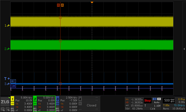
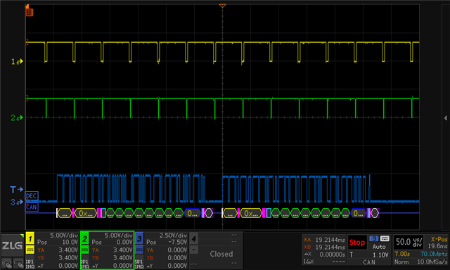
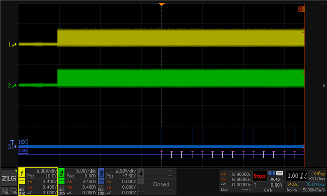
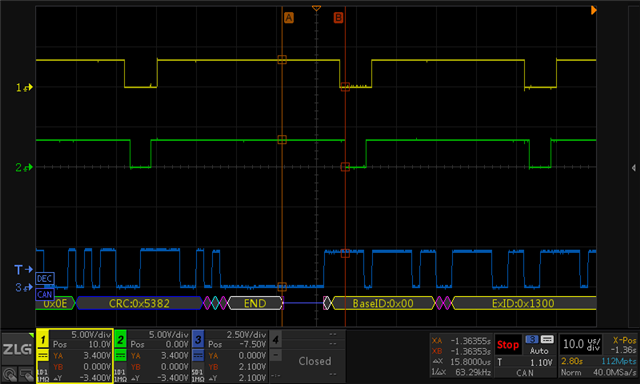
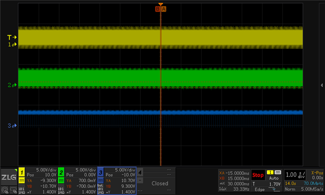
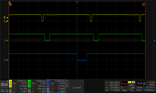
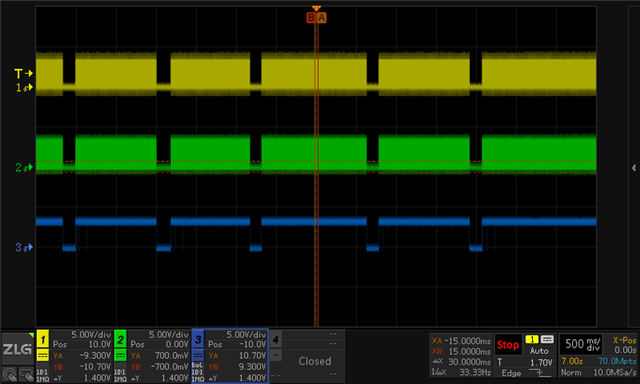
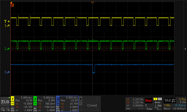
  • I am using two IOs as relevant indicators:
    1)Dio_ISR, oscilloscope channel 1,[yellow]
    2)Dio_HWBIST, oscilloscope channel 2,[green]
    3)Differential signal of CANH and CANL, oscilloscope channel 3,[blue]

    The relevant interrupt code is as follows:

    __interrupt void INT_CtrlTimer_ISR(void)
    {
        GPIO_writePin(Dio_ISR, 0);
    
        static uint16_t TimerCnt1s=0;
        static uint16_t TimerCnt1ms=0;
    
        TimerCnt1s++;
        if(TimerCnt1s>=20000)
        {
            TimerCnt1s=0;
            OsEmu_BswDio_Flag=1;
        }


        GPIO_writePin(Dio_HWBIST, 0);
    
        /* Case 1: call BswHWBIST_Inst() in while(1) every 50us */
        //OsEmu_BswHWBIST_Flag=1;
        /* Case 2: call BswHWBIST_Inst() here in the control ISR */
        BswHWBIST_Inst();
        GPIO_writePin(Dio_HWBIST, 1);


        // Acknowledge this interrupt to receive more interrupts from group 1
        Interrupt_clearACKGroup(INTERRUPT_ACK_GROUP1);
        GPIO_writePin(Dio_ISR, 1);
    }

    Test 1: HWBIST_Micro is called every 50us in while(1), and the CAN card sends a CAN frame every 500ms and receives a response frame. The waveform is as follows:

    Test 2.1: HWBIST_Micro is called immediately in the 50us interrupt. Power on the development board first, and send a CAN frame after 10s. No response frame is received upon the first transmission.

    Test 2.2: Start sending the 0x1200 frame on the CAN card first, and then power on the development board. It can be seen that after receiving two response frames, recovery is no longer possible.
    Note: Because the controller is not powered on when the CAN card is started alone, there is no response field. Therefore, the frame interval at the moment of startup is not 500ms.

    The last send and response frame waveform is as below

  • If there is any new information on this issue?

  • Thanks for your patience. I haven't been able to get the hardware to run your test case yet.

    Thanks for sharing the detailed scope captures. Unfortunately I'm not familiar enough with CAN to know precisely where the interrupt occurs to know whether or not the issue is caused by the HWBIST interrupt logger. Are you able to also toggle an pin in the CAN ISR and show that instead of the frame waveform?

    You had mentioned earlier in the thread that you can Interrupt_clearACKGroup() to get CAN interrupts to reissue the interrupt. Are you able to add that to your timer ISR for now as a workaround at least while we try to determine the actual cause of the issue?

    Whitney

  • 1)Recently I don’t have a development board on hand either; I will find time to conduct relevant tests as soon as possible.
    2)I think this issue may not be related to a CAN interrupt occurring during HWBIST execution, because if it was related, when I execute HWBST_RunMicro every 50 μs in the while(1) loop, a CAN interrupt could also occur during HWBIST execution, causing subsequent CAN interrupt anomalies.
    3)I suspect it might be related to executing HWBIST inside an interrupt.
    4)Our product has already entered small‑scale production; the testing department will not allow continuously clearing interrupt flags in a periodic interrupt. Moreover, our design involves not only CAN but also peripherals and interrupts, etc. I need to know how to call HWBIST safely without affecting other modules.

  • I'm not sure if the test you want me to run matches the description below. No ISR nesting is used here. Test environment introduction:
    ->Dio_ISR, oscilloscope channel 1, [yellow]
    ->Dio_HWBIST, oscilloscope channel 2, [green]
    ->Dio_CANISR, oscilloscope channel 3, [blue]

    1)The 50 µs control interrupt code is as follows. In the interrupt, Dio_ISR is toggled:

    __interrupt void INT_CtrlTimer_ISR(void)
    {
        GPIO_writePin(Dio_ISR, 0);
    
        static uint16_t TimerCnt1s=0;
        static uint16_t TimerCnt1ms=0;
    
        TimerCnt1s++;
        if(TimerCnt1s>=20000)
        {
            TimerCnt1s=0;
            OsEmu_BswDio_Flag=1;
        }
    
        /* Case 1: call BswHWBIST_Inst() in while(1) every 50us */
        OsEmu_BswHWBIST_Flag=1;
        /* Case 2: call BswHWBIST_Inst() here in the control ISR */
        //BswHWBIST_Inst();
    
        // Acknowledge this interrupt to receive more interrupts from group 1
        Interrupt_clearACKGroup(INTERRUPT_ACK_GROUP1);
        GPIO_writePin(Dio_ISR, 1);
    }

    Case 1: Execute BswHWBIST_Inst() in while(1) every 50 µs.
    Case 2: Execute BswHWBIST_Inst() directly in the 50 µs control interrupt.

    2)The BswHWBIST_Inst() function is as follows, This function toggles Dio_HWBIST.

    void BswHWBIST_Inst(void)
    {
        GPIO_writePin(Dio_HWBIST, 0);
        HWBISTTimes++;
        uint16_t returnVal = 0;
    
        /* Run a micro-run of HWBIST */
        returnVal = STL_HWBIST_runMicro();
    
        /* Result Handle */
        if(STL_HWBIST_MACRO_DONE == (returnVal & STL_HWBIST_MACRO_DONE))
        {
            if( (returnVal & ~(STL_HWBIST_BIST_DONE | STL_HWBIST_MACRO_DONE))!= 0 )
            {
                //Fail
                GPIO_writePin(FaultLED_GPIO,0);
            }
            else if( STL_HWBIST_BIST_DONE == (returnVal & STL_HWBIST_BIST_DONE) )   //STL_HWBIST_BIST_DONE
            {
                STL_HWBIST_init(STL_HWBIST_90_LOS);
            }
            else        //STL_HWBIST_MACRO_DONE
            {}
        }
        else
        {
            //Fail
            GPIO_writePin(FaultLED_GPIO,0);
        }
    
        OsEmu_BswHWBIST_Flag=0;
        GPIO_writePin(Dio_HWBIST, 1);
    }

    3)The CAN interrupt function is as follows, this function toggles Dio_CANISR.

    __interrupt void INT_BswCan_CANA_1_ISR(void)
    {
        static uint32_t status;
        static uint16_t tempBuffer[8]={1,2,3,4,5,6,7,8};
    	
    	GPIO_writePin(Dio_CANISR, 0);
        status = CAN_getInterruptMessageSource(BswCan_CANA_BASE);
        
    	if((status>>0)&0x01)
        {
            tempBuffer[0] = HwBISTTimes;
            CAN_sendMessage(BswCan_CANA_BASE, 2, 8, tempBuffer);
            CAN_clearInterruptStatus(BswCan_CANA_BASE, 1);
        }
    
        CAN_clearGlobalInterruptStatus(BswCan_CANA_BASE, CAN_GLOBAL_INT_CANINT1);
        Interrupt_clearACKGroup(INTERRUPT_ACK_GROUP9);
        GPIO_writePin(Dio_CANISR, 1);
    }

    Test 1: transmit can message from PC every 100ms, it will continue response.

    Test 2: transmit can message from PC every 100ms,.After the DSP is reset, it will respond for a few frames and then stop responding.

  • I have designed a simplified test that replaces the CAN interrupt with an ePWM periodic timer interrupt. In the ePWM interrupt, an I/O pin toggles a breathing LED.
    Calling HWBIST every 50 µs in the while(1) loop does not affect the entry of the ePWM interrupt. However, if HWBIST is called directly in a 50 µs control interrupt, the ePWM interrupt stops being triggered after a short period of operation.3007.empty_driverlib_project.rar

  • Thanks for sharing the screen captures and the updated project. It's helpful to know it can also be reproduced with the PWM interrupt. That should be easier to debug with than trying to generate CAN interrupts. I expect I'll be able to run your test code tomorrow and will update you with the behavior I observe.

    Whitney

  • I have a theory after doing some experimenting. When an interrupt occurs, the CPU will set INTM and clear the IER bit for the triggered interrupt before fetching the ISR vector. When the STL_HWBIST_runMicroTest function runs, it enables interrupt logging, effectively disabling interrupts as well and then waits for several cycles for already propagating to execute before telling HWBIST to start running. The STL_HWBIST function makes sure to back up the IER register before executing HWBIST, but it does not back up IFR because it's assumed any enabled interrupts will execute before HWBIST is triggered.

    After HWBIST micro run finishes, it seems IFR is cleared. If an enabled interrupt occurred during HWBIST, the interrupt logger will reissue it, setting the corresponding IFR bit.

    What this doesn't account for is the case where you call STL_HWBIST_runMicro from an ISR where interrupts are disabled by default and therefore any pending interrupts in IFR (say if the CAN interrupt was triggered right after the Timer interrupt), won't have a chance to run before HWBIST clears them all.

    I assume in the use case where you had nesting enabled, that you were enabling INTM (I see the EINT in your code), but the IER mask didn't allow the CAN interrupt to run?

    I think there are three options to fix this (and these seemed to work when I tested them):

    1. Run HWBIST from your lowest priority interrupt with nesting enabled so any pending interrupts in IFR get a chance to run to before HWBIST starts.

    2. Back up IFR and restore it after HWBIST completes. I tested this by editing stl_hwbist_s.asm to replace the ASP instruction with PUSH IFR and the NASP instruction with POP IFR and it seemed to work.

    3. When you see the IFR bit is 0 and the PIEIFR bit is 1, set PIEACK to allow it to propagate to IFR again.

    So you can try those options and see how they work for you.

    Whitney

  • Okay, without considering interrupt nesting, can it be understood that if a CAN interrupt happens right after a timer interrupt, both the IFR (CAN) and IFR (TIMER) are set. Then, in the timer interrupt, STL_HWBIST_runMicro is called. After the HWBIST execution completes and resets, the IFR (CAN) is automatically cleared, so the CAN interrupt is not serviced.

    Since our product has entered small-scale production and we have also adopted interrupt nesting-related designs. Based on your experience, is calling STL_HWBIST_runMicro in the while(1) loop the safest solution that will not affect other interrupts?

  • The while loop is probably the safest for now, but I understand if it's not feasible for how frequently you want to run the test. Of the options I listed above, #2 is probably the one we'll implement as our bug fix for this issue, but I think it needs a little more testing to make sure we haven't missed any edge cases. If you try it, let us know how it works for you.

    Whitney

  • Thank you very much. In our product's code, we temporarily use a while(1) loop to call HWBIST.

    Option listed above #1: In a design with interrupt nesting, run HWBIST in the lowest-priority interrupt, ensuring that all pending interrupts are fully executed before executing HWBIST. This is similar to calling it in a while(1) loop, with only some differences in time jitter.

    Option listed above #2: I tested this on the 0039 control card. After modifying the assembly code, HWBIST is called directly in the control interrupt. Currently, both the CAN interrupt and the ePWM interrupt can be entered without being affected.