This thread has been locked.

If you have a related question, please click the "Ask a related question" button in the top right corner. The newly created question will be automatically linked to this question.

TMS320F280037C: GPIO source current all pins

Guru 56418 points

Part Number: TMS320F280037C

Hello,

Regarding electrical specification please explain what -4mA high source current represents? What is the MAX high source current on any GPIO pin? This table makes not sence to know what an LED can be safely driven by high output voltage sinking current into the GPIO peripheral. It seems we can use the low level sink 4mA though it would be nice to know how much is maximum high source current.
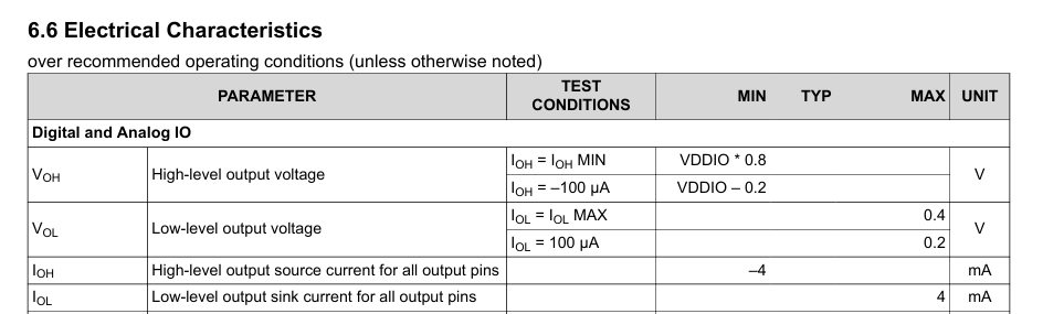
image.png

  • Hi Genatco,

    The negative sign in IOH = -4mA is a convention indicating current direction — it means current flowing out of the pin (sourcing). This is not a maximum limit but rather a guaranteed minimum test condition: the GPIO can source at least 4mA while still maintaining VOH ≥ VDD - 0.45V 1.

    Maximum High Source Current

    The answer depends on which device and pin type you're using:

    Pin Type Drive Settings Available Max IOH (Source)
    Standard GPIO (most pins) 2mA / 4mA / 6mA 6mA
    Pins 29, 30, 45, 50, 52, 53 2mA / 4mA / 6mA 3.5mA (at 6-mA drive setting)
    FAST GPIO pads (some devices) 2/4/8/10/12mA 12mA

    For standard GPIO pins, the specifications are symmetrical — IOH (source) and IOL (sink) support the same drive strength settings (2/4/6mA) 2.

    Critical Point for LED Driving

    TI explicitly states that GPIO outputs were not designed to drive LEDs directly 3. The IOH/IOL values represent current available during signal transitions (charging/discharging capacitance), not steady-state DC current for loads like LEDs. Driving constant current can create long-term reliability concerns.

    TI's recommendation: Use an external transistor or FET to drive the LED, controlled by the GPIO output 3.

    Why No "MAX" Current is Published

    TI does not define an absolute maximum GPIO current because driving an output into a steady-state load beyond the specified IOH/IOL is not a validated use case. Exceeding these values is considered Electrical Over-Stress (EOS) and may damage the device 1.


    1. AM2432: GPIO MAX output current - TI E2E
    2. CC3220 Technical Reference Manual - I/O Pad Electrical Specifications
    3. GPIO Design Recommendations FAQ - TI E2E

    Best Regards,

    Zackary Fleenor

  • HI Zackary,

    Thank you for this answer though the x39c TRM didn't seem to have the table you provided or it was not in the electrical specification section. I used the low sink current to drive both LED flashing states and 680Ω series resistor. The LED datasheet test illumination 20mA and had driven them <4mA pad strength on another MCU and maintained very bright toggled flash state.

    FYI, accidently caused a solder short VDD to ground and MCU started to quickly heat <85°c well after being flashed and toggling two LED for hours. Thought surely had bricked the MCU but that was not the case. After clearing short across 0402 capacitor, it was fully functional and flashed firmware several times since. It must have been current to ground, but from where did the current originate VDDIO or the two LED.  

    Regards,

  • Hi Gentaco,

    Your configuration — sinking <4mA through a 680Ω series resistor with the GPIO driving low — is within the specified IOL capability. At 3.3V VDDIO with a typical LED forward voltage of ~2V, you'd see approximately (3.3V - 2V - 0.4V) / 680Ω ≈ 1.3mA, well within spec.

    However, TI explicitly states GPIOs are not designed for steady-state DC loads like LEDs 2. The IOH/IOL values represent transient drive capability. For production designs, an external transistor is recommended.

    Regarding the VDD-to-Ground Short

    The current that caused heating almost certainly originated from VDDIO (the 3.3V supply rail), not the LEDs. A solder short across a decoupling capacitor between VDD/VDDIO and ground creates a direct supply-to-ground path — the power supply attempts to drive unlimited current through that short. The absolute maximum ratings specify that exceeding conditions may cause permanent damage, though your device survived due to the relatively brief duration and thermal protection characteristics 3.

    Caution: TI states that operation outside absolute maximum ratings "may affect device reliability, functionality, performance, and shorten the device lifetime". While the device appears functional now, latent damage from the thermal/electrical overstress event cannot be ruled out. Consider this unit a prototype/development board only.

    Best Regards,

    Zackary Fleenor

  • Hi Zackary,

    However, TI explicitly states GPIOs are not designed for steady-state DC loads like LEDs 2. The IOH/IOL values represent transient drive capability. For production designs, an external transistor is recommended.

    Actually, this is the first time in years developing with TI micros ever read about this limitation. Past developing around Tiva TMS320F1294KCPDT class of MCU launch pads, never had any external LED drivers. Earlier Stellaris class MCU at one time even had +5v tolerant GPIO's drove LED direct from GPIO pins. It was only recently LaunchXL-39c/49c schematics show LED driver.

    Given this updated information will certainly provide space for LED driver IC. 

    Thank you for your support (;-)