Part Number: TMS320F280037C
Other Parts Discussed in Thread: C2000WARE
Hello,
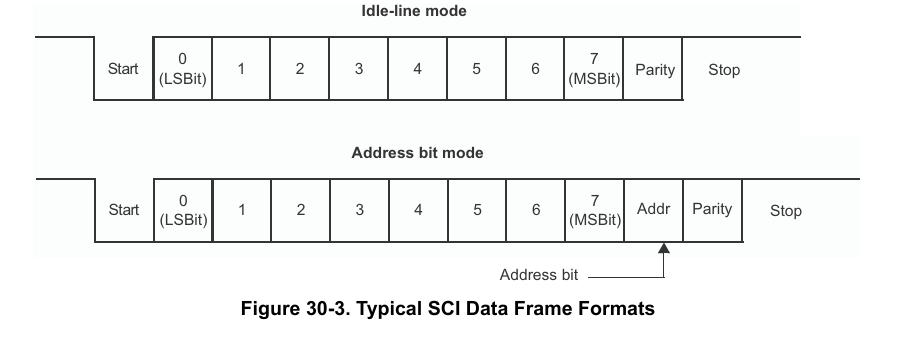
Theses are similar questions to previously answered ones but more relative to adding 1 bit and the tables when more than 10 bits exist in a single frame. The example below shows 11 bits when no multiprocesor feild address bit time is required.
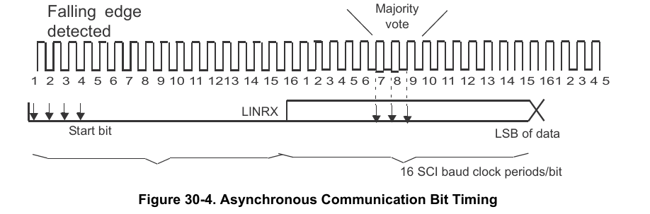
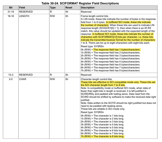
Why do the other tables below not show an typical 11 bit field frame as to keep consistent with the very first frame layout Fig 30-3. This why there is so much confusion! Does the Lin mode 2 frame example Fig. 30-4 (Majority Vote) require we configure 2 frames lengths for LIN module, (LINRX) total of 16 bits for SCI mode emulation?
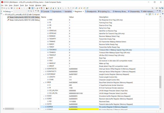
Are we to assume odd/even parity relates to 0 /1 respectively? And Addr 0 means ignore in the sub fractional bit modulation M divisor table 30-2? I assume BRS 31:28 is 2h for 11 bits? These TRM examples are very confusing relative to Lin.h module LIN_setBaudRatePrescaler().
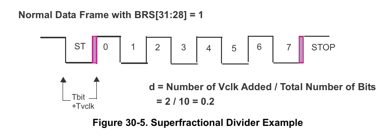
SYSCLK for the LIN peripheral clock = 120mHz and need to match RX frames of another MCU UART 9600, 8, even, 1 stop or 11 bits. Table 30-2 is it a fixed frame layout on each line or dynamic relative to total bits being used in Figure 30-5?
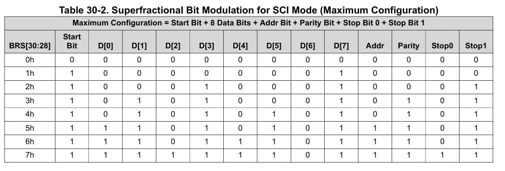
One extra bit (10 +1) makes these tables very confusing: And d=1 / 11 = 0.090909090909~
The above table lead me to believe also need to subtract the extra Addr bit when SCICom mode is Idle line? Seem to recall with Even parity the high order bit is set and Odd parity bit would be clear? Does one stop bit need to be subtracted too from Fig. 30-5 from maxium configuration table or again is table 30-2 fixed, non modifiable. LIN_setSCICommMode(LINA_BASE, LIN_COMM_SCI_IDLELINE);