This thread has been locked.

If you have a related question, please click the "Ask a related question" button in the top right corner. The newly created question will be automatically linked to this question.

Current measure using the Hall sensors

Other Parts Discussed in Thread: MOTORWARE, TMS320F28069F, CONTROLSUITE, TMDSHVMTRINSPIN

Hi,

I use InstaSPIN FOC in my new design and I am trying to measure current with 3 Hall sensors.

My motor is: ACIM, 5,5kW

I define USER_IQ_FULL_SCALE_CURRENT_A, USER_ADC_FULL_SCALE_CURRENT_A, USER_IQ_FULL_SCALE_VOLTAGE_V, USER_ADC_FULL_SCALE_VOLTAGE_V correctly.

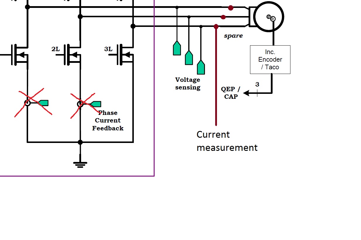
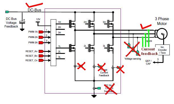
I didn't connect the sensors to transistors which are connected to the GND, but directly to the 3 phases of the motor.

So, I started the motor as it is explained in the PDF file but measured parameters of the identification are incorrect.

My question is what I have to define in the CCS program for correct current measurement?

Thank you!

  • with pase current sensors you only need to use two, using a third isn't necessary at all for the measurements, but I suppose you could sample this third channel and use it to check that you aren't having issues with the other two.

    if you use 2 or 3 the only change you need to make is in your user.h

    #define USER_NUM_CURRENT_SENSORS            (3)


    What sort of precautions / checks did you do to insure your sensors are working correctly?  I would use DC currents to check your +/- current range and make sure you are getting expected results through your scaling to 0-3.3Vdc to the ADC pins and then for your ADC conversions.

    Are you using the same ADC pins that we do on the controlCARD+kit? If not, you need to reconfigure your drv file to the proper channels.

    Have you verified the analog hardware for the phase and bus voltage as well? All 6-7 of the analog inputs into the sysem are critical for success.

    Have you looked at your ADC offset calibration? Does it seem reasonable like the lab examples explain?


  • Thank you  for your answer.

     I defined:

    #define USER_NUM_CURRENT_SENSORS            (3)

    I have amplifiers after the sensors with offset 1.65. I checked the Hall sensors with DC current and did the measurements with oscilloscope which is connected to the amplifiers end. I have checked my connections in the board - everything is connected as it  should and the scaling is in range.

    I used the same ADC pins as you do on the controlCARD+kit. I have calculated the voltage dividers and the capacitor  placed nearby to be in range (0-3.3V) and defined:

    #define USER_VOLTAGE_FILTER_POLE_Hz  (342.18) // this value is in my case

    The voltage and current values are defined correctly in CCS.

    I don't have sensor on the DC bus. Is it possible to do the identification and the value calculation without it?

    Here you can see how I connected the hall sensors:

  • I just tried this and it works. In mainISR, I added the highlighted code:

    // convert the ADC data

    DRV_readAdcData(drvHandle,&gAdcData);

    // disable DC bus compensation

    CTRL_setFlag_enableDcBusComp(ctrlHandle, false);

    // overwrite dcbus with 0 to prove this works with no dcbus feedback.

    gAdcData.dcBus = _IQ(0.0);

    // run the controller

    CTRL_run(ctrlHandle,drvHandle,&gAdcData,&gPwmData);

    As long as the dcbus enable flag is set to false, the dcbus feedback can be ignored. Keep in mind that if you have dc bus variations, the current controllers will not compensate for that.

  • Thank you for your answer.

  • I have one more question. My design doesn't have the DC BUS current sensor, so I'm not measuring Ifb, but I do measure the DC BUS voltage. Could I leave it this way or do I need to add it too? What should I change in the program? Also I'm not sure that my current sensors are at the correct place - I've placed them directly on the three phase outputs to the motor, instead of as it is in the kit's circuit.

    Thank you very much for your time.

  • DC Bus current is not used in the algoritm. Some people use it for an over current detection, that is up to you.

    If you have a DC Bus measurement you should use it, it is part of the default MotorWare projects.  This lets you turn on DC Bus compensation, meaning instead of just putting a duty cycle on the inverter which produces a % of bus, you can insure it creates an exact voltage to the motor phases.

    Yes, if doing phase current measurement using a hall type (LEM is the most popular brand) these go in-line to the phases. It may be built onto your PCB or I have seen some retrofits that allow the phase wires to just pass through, like a current probe.


  • Dear chris,

    I am using TMS320F28069F. I started to implement FOC algorithm in my existing board for AC induction motor for 415V/50Hz system. I refer motorware examples and manual.

    In my board 3 current sensor and 1 DC bus voltage feddback are available.

    We dont have output voltage feedback in my board. Is it possible to do the motor identification and the value calculation without it?

    In general AC drive system there are no facility of output voltage feedback, so is this necessary for develop this FOC algorithm? If voltage feedback required, than what is option availabe for my application? And how i implement this algorithm for my system? And what are the changes require in programme?

    Here below image shows my system and feedback of system (1 DC voltage and 3 current feedback).


  • The InstaSPIN-FOC solution requires the phase voltage measurements. These should be easy to add, just a simple resistor divider with a filter.

  • Thank you  for your answer.

    But these added extra circuit in our existing control  board.

    So, is there any other best solution for the FOC implement without output voltage measurement.

  • using the FAST observer requires the voltage feedback.

    the SMO (or eSMO) observer in controlSUITE does not required voltage feedback.  It does require some expertise and know-how.

    If you are not an expert it is very worth your time to add the voltage feedback for FAST.


  • it is quite difficult to use output voltage feedback circuit in my board as output of our inverter is 690V (960V peak) and dv/dt noise is very high. It create some EMI problem in our board.

    So, i want to use SMO module.can you give some information of SMO module for implement. 

  • You can find information about the SMO and eSMO in controlSUITE, specifically the HVKIT v2.1

    Some thoughts on high voltage dv/dt

    On high voltage systems EMI can be a pain if things are done sub-optimaly.  Use high voltage differential attenuators with an instrumentation amplifier to get what you need: no noise on your sampled data and good linearity.

    • From two high voltage inputs: make two identical resistive voltage dividers (preferably 0.1% tolerance) dividing 600V into 10V or so to the local ground of the control board. Use many resistors in series to get sufficient voltage capability. Total divider: 3M  / 30k type ratio. No ground planes under the dividers!!! 
    • Connect the two divided voltages to the input of a good instrumentation amplifier (AD620 or the like, fed with sufficient supply voltage +/- 10 or 15V) and place the low pass capacitor (low tolerance, stable type) across the two amplifier inputs to get the required voltage filter pole. A small cap on each input to ground to avoid HF common-mode saturating the opamp (>100 times the filter pole).
    • Output of the instrumentation amplifier is +/- 10V or the like, attenuate and add half full scale of AD input with four resistors of a couple of k Ohms, add a 1nF directly at the AD input to keep HF out.
    • This way you get 0-3.3V projection of the differential voltage between the two high voltage inputs, first order filtered at the required pole. DC true, high input impedance (not infinite), substantial common mode input voltage allowable (up to 1kV or up if required). Sensitivity of differential attenuator can be enlarged by placing a gain resistor at the instrumentation amplifier.

    This way you get excellent voltage measurement quality, and noise free low impedance drive of the AD input. Customers have used it on 400V systems without any issues for the last 10 years, and one right now uses it on 1000V systems  with superb results: (less than 1LSB noise on AD data when having 1000V common mode square wave on inputs with extreme dV/dt's on a 250kW inverter output).

  • Thank you chris,

    It is not possible to accommodate high voltage feedback circuit in our new board.

    Our exciting product is already work with 28069 and we want replace with 28069F controller because of FOC features. 

    So please can you give me some more guide line to implement FOC without output voltage feedback.

  • Amtech,

    our sliding mode observer techniques do not require phase voltage feedback. i recommend reviewing from www.ti.com/tool/controlsuite

    C:\ti\controlSUITE\development_kits\HVMotorCtrl+PfcKit_v2.1\HVPM_Enhanced_Sensorless_2803x


  • Chris,

    I made some changes of my kit design. I changed the position of the hall sensors to the original kit design. Now I try to identify my motor with proj_lab02a.

    The problem is that some values isn't correct. My ACIM motor is 100V.

    gMotorVars.Rs_Ohm ~ 70 Ohm - I think that this is normally for my induction motor

    but  gMotorVars.Lsd_H  and  gMotorVars.Lsq_H   ~ 0.1 uH  I think this is very low for my induction motor.

    I measured correctly  gMotorVars.VdcBus_kV.

    When Initialization finished, I start the motor again  (and set gMotorVars.Flag_Run_Identify = 1) but rotor isn't rotate with reference speed which I set in gMotorVars.SpeedRef_krpm. The rotor rotating speed is very low, so I can't  increase the speed to maximum.

    What could be the problem?

    Thank you!


  • Pavel,

    The motor ID capability for ACI Motors is not functioning reliably through MotorWare _11.  If you happen to know your motor parameters you should bypass Motor ID and just enter and load the values from user.h

    With proper motor parameters the control works as expected, even with _11.

    We have identified and fixed all issues on the ACI Motor ID topic and will make them available in MotorWare _12, which will release end of February.

    I apologize for this not working correctly for you today.


  • Thank you Chris !

  • Chris

    I try to set the parameters for my ACIM motor in  user.h  but I can't achieved RPM control. When I set

    gMotorVars.SpeedRef_krpm   to    ZERO,     the motor is in a brake mode, in other value motor start to rotate with constant default speed but not whit that I set. And when the value is negative the motor reverse his direction with the same constant default speed.

    It's important !


    Thanks!


  • your parameters are incorrect.

    did you try to calculate from the motor nameplate?

    http://e2e.ti.com/support/microcontrollers/c2000/f/902/t/318299.aspx


    you will be able to ID your ACI through MotorWare project within a few weeks in the MotorWare _12 release. We have this fixed.


  • Thank you very much Chris for your answer!

    My ACIM motor is not a standard one and I don't have datasheet, so I tried to calculate its parameters, but without success.

    I hope the MotorWere_12 will help me.

  • We have this working quite well with the TMDSHVMTRINSPIN kit, and we think for all "normal" induction motors. This will be in _12 on March 4th.

    We are still working through things on ACI Motor ID for the DRV83x kits, where high current induction motors would be used.  The inductance test still has some tuning to make sure it works across all motors (and there are a WIDE variety of low voltage ACI motors of various current levels - lots of custom designs).  It doesn't look like we will get this portion sorted for _12, but we will get it fixed by the next release (or post something on the forums as soon as avialable).