This thread has been locked.

If you have a related question, please click the "Ask a related question" button in the top right corner. The newly created question will be automatically linked to this question.

Unable to Debug examples to my TMS320F28035 (ERROR 1135)

Other Parts Discussed in Thread: TMS320F28035, UNIFLASH, CONTROLSUITE, TMDSCNCD28035ISO

Hi,


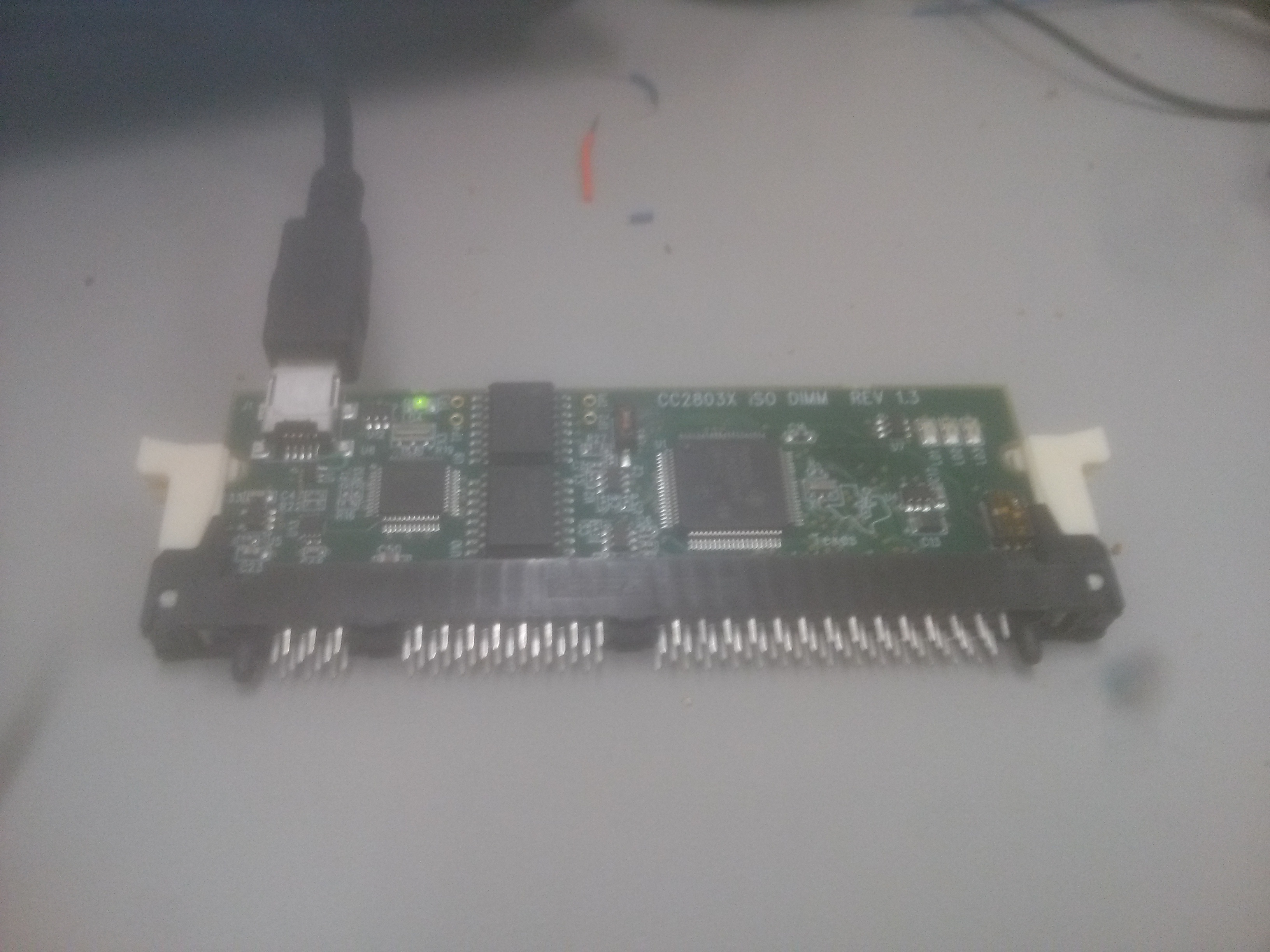
I have downlaoded Code Composer Studio version:5.5.0.00077. I have "TMS320F28035 Isolated controlCARD" and the link is here: http://www.ti.com/tool/tmdscncd28035iso

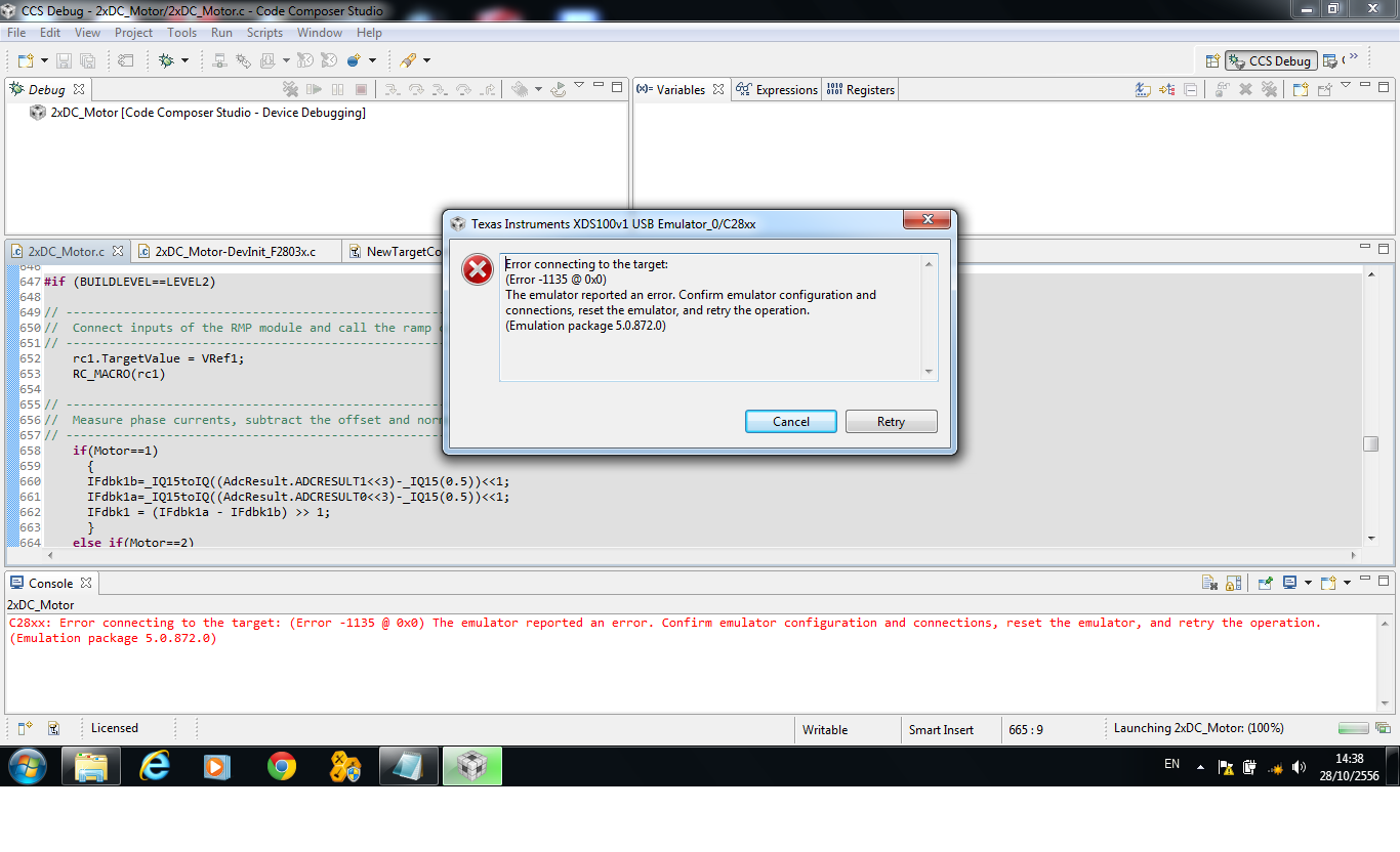
I watched some turotiral on how to use CCS5 and step-by-step intructions on building and debugging. However, whenever I try to debug any code ( Used some example code from ControlSuit) , I get the following error:

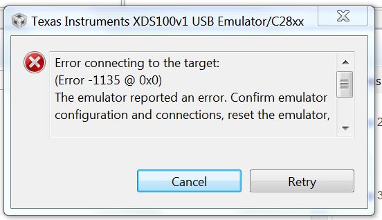
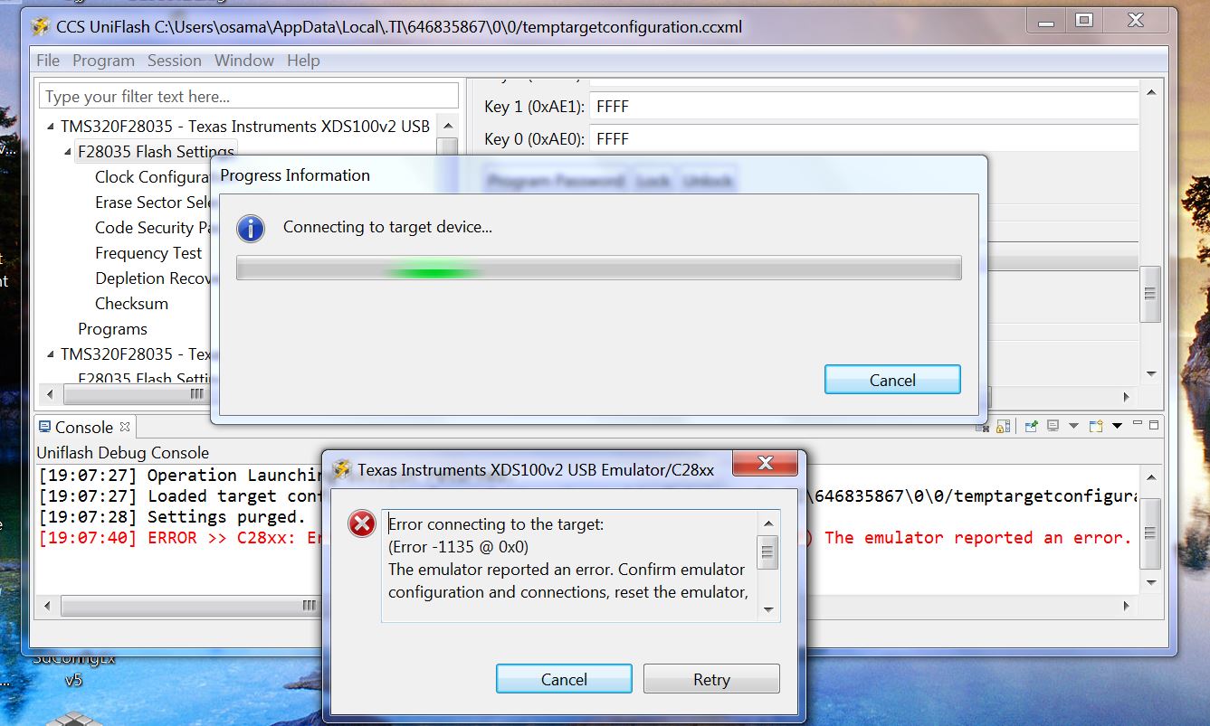
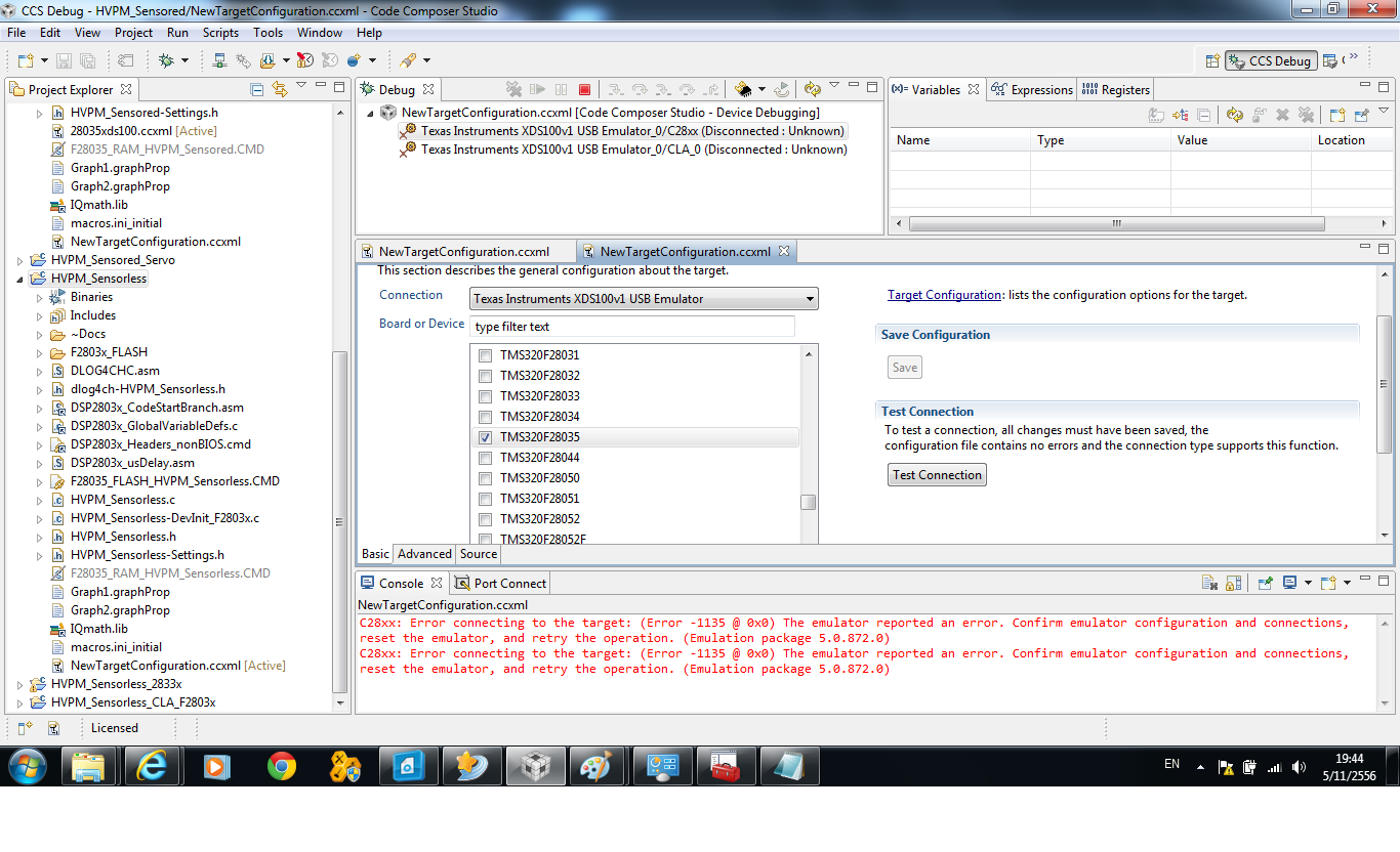
"C28xx: Error connecting to the target: (Error -1135 @ 0x0) The emulator reported an error. Confirm emulator configuration and connections, reset the emulator, and retry the operation. (Emulation package 5.1.232.0) "

I searched online for possible soultions and I did the flollwoing to fix the problem:

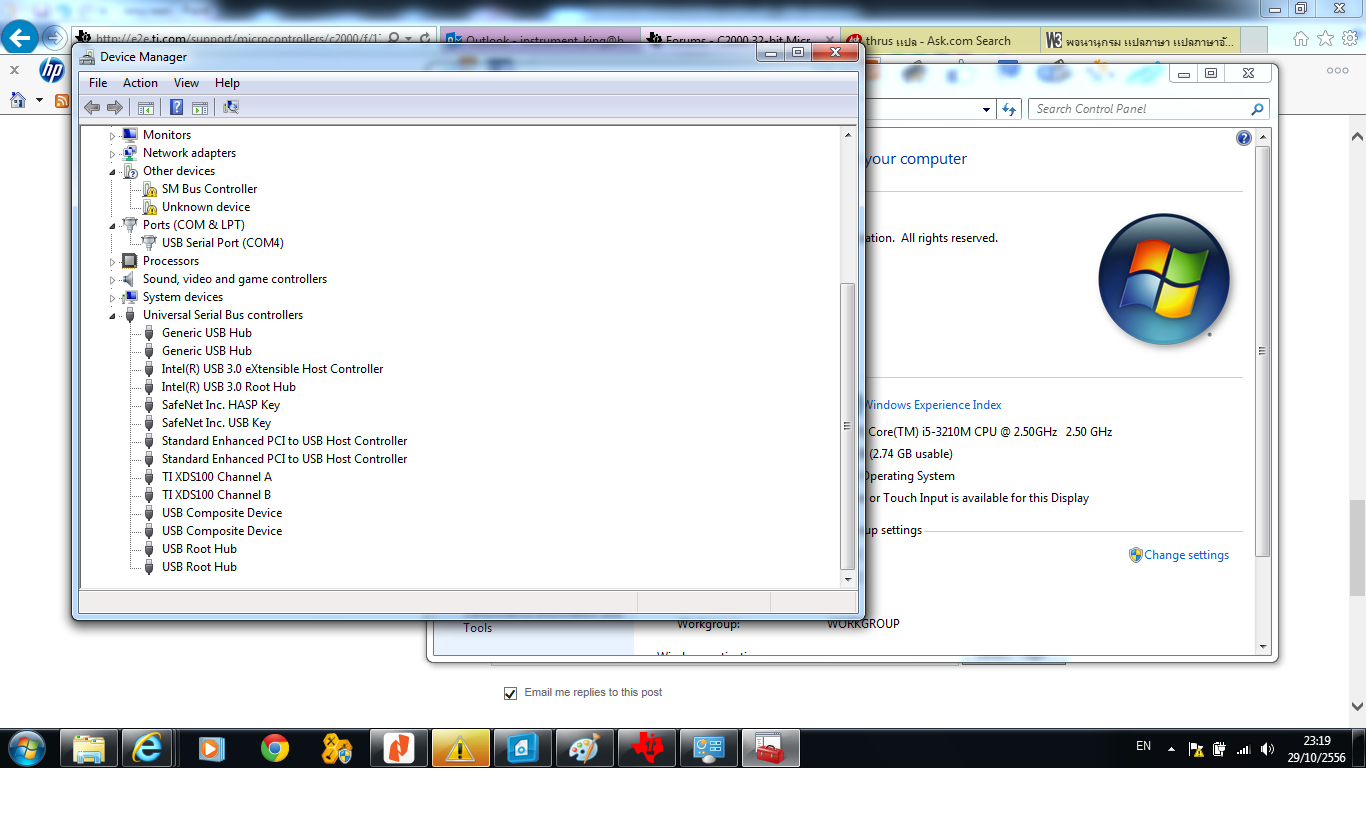
  • Checked my USB connection through Device Manager
  • I chose the right connection/emulator in CCS5 which is XDS100v1
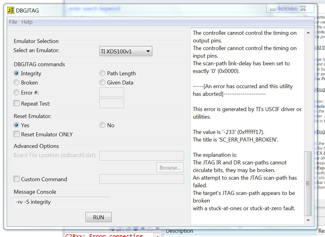
  • Downloaded DebugJTAG software 
  • Re-installed CCS5

I still have the same problem. I attached two images of the error. One from CCS5 and the other one is from DebugJTAG software.


I am hoping you can help me with some hints on how to deal with this problem. 

Thank you,
Osama Abuassonon
  • Hi,

    Did you check your device manager? Is the emulator driver installed correctly?

    Regards,

    Gautam

  • Hi Gautam, 

    Yes I did. It shows: TI XDS100 Channel A and TI XDS100 Channel B.

    Thanks,

    Osama  

  • Hi,

    Can you try by selecting emulator as "XDS100 v2" in the configuration window?

    Regards,

    Gautam

  • I did try this already! I also tried XDS100 V3.

  • Finally you can try with CCS Uniflash and check whether the error repeats.

    Regards,

    Gautam

  • Hello Gautam,

    I have tried using Uniflash. Whenever I choose to do the frequency test, it gives me same error as I had with CCS. Attached an image of that error. 

    BTW, I actually used two different USB cable to make sure the problem is not with the cables. 

    Regards,

    Osama

  • Hi,

    Did you check with the voltage levels on the docking station? As the FTDI chip is mounted on the station, please check with regulator outs etc.

    Regards,

    Gautam

  • Hi

    I have problem same you.

  • Wiwat, check with the target configuration first and then check the voltage levels on the docking station.

    Regards,

    Gautam

  • Hi

    Thank you very much for Email.I'm tried follow start guide.And changed XDS100v1 to  XDS100v2 and  XDS100v3.Result is same prolbem.I'm check voltage at Capacitor 41=3.3v and Capacitor 44=5v and at USB connector=5v 

    [Start]
    
    Execute the command:
    
    %ccs_base%/common/uscif/dbgjtag -f %boarddatafile% -rv -o -F inform,logfile=yes -S pathlength -S integrity
    
    [Result]
    
    
    -----[Print the board config pathname(s)]------------------------------------
    
    C:\Users\PC\AppData\Local\.TI\693494126\
        0\0\BrdDat\testBoard.dat
    
    -----[Print the reset-command software log-file]-----------------------------
    
    This utility has selected a 100- or 510-class product.
    This utility will load the adapter 'jioserdesusb.dll'.
    The library build date was 'Oct  3 2012'.
    The library build time was '21:58:41'.
    The library package version is '5.0.872.0'.
    The library component version is '35.34.40.0'.
    The controller does not use a programmable FPGA.
    The controller has a version number of '4' (0x00000004).
    The controller has an insertion length of '0' (0x00000000).
    This utility will attempt to reset the controller.
    This utility has successfully reset the controller.
    
    -----[Print the reset-command hardware log-file]-----------------------------
    
    The scan-path will be reset by toggling the JTAG TRST signal.
    The controller is the FTDI FT2232 with USB interface.
    The link from controller to target is direct (without cable).
    The software is configured for FTDI FT2232 features.
    The controller cannot monitor the value on the EMU[0] pin.
    The controller cannot monitor the value on the EMU[1] pin.
    The controller cannot control the timing on output pins.
    The controller cannot control the timing on input pins.
    The scan-path link-delay has been set to exactly '0' (0x0000).
    
    -----[The log-file for the JTAG TCLK output generated from the PLL]----------
    
    There is no hardware for programming the JTAG TCLK frequency.
    
    -----[Measure the source and frequency of the final JTAG TCLKR input]--------
    
    There is no hardware for measuring the JTAG TCLK frequency.
    
    -----[Perform the standard path-length test on the JTAG IR and DR]-----------
    
    This path-length test uses blocks of 512 32-bit words.
    
    The test for the JTAG IR instruction path-length failed.
    The JTAG IR instruction scan-path is stuck-at-ones.
    
    The test for the JTAG DR bypass path-length failed.
    The JTAG DR bypass scan-path is stuck-at-ones.
    
    -----[Perform the Integrity scan-test on the JTAG IR]------------------------
    
    This test will use blocks of 512 32-bit words.
    This test will be applied just once.
    
    Do a test using 0xFFFFFFFF.
    Scan tests: 1, skipped: 0, failed: 0
    Do a test using 0x00000000.
    Test 2 Word 0: scanned out 0x00000000 and scanned in 0xFFFFFFFF.
    Test 2 Word 1: scanned out 0x00000000 and scanned in 0xFFFFFFFF.
    Test 2 Word 2: scanned out 0x00000000 and scanned in 0xFFFFFFFF.
    Test 2 Word 3: scanned out 0x00000000 and scanned in 0xFFFFFFFF.
    Test 2 Word 4: scanned out 0x00000000 and scanned in 0xFFFFFFFF.
    Test 2 Word 5: scanned out 0x00000000 and scanned in 0xFFFFFFFF.
    Test 2 Word 6: scanned out 0x00000000 and scanned in 0xFFFFFFFF.
    Test 2 Word 7: scanned out 0x00000000 and scanned in 0xFFFFFFFF.
    The details of the first 8 errors have been provided.
    The utility will now report only the count of failed tests.
    Scan tests: 2, skipped: 0, failed: 1
    Do a test using 0xFE03E0E2.
    Scan tests: 3, skipped: 0, failed: 2
    Do a test using 0x01FC1F1D.
    Scan tests: 4, skipped: 0, failed: 3
    Do a test using 0x5533CCAA.
    Scan tests: 5, skipped: 0, failed: 4
    Do a test using 0xAACC3355.
    Scan tests: 6, skipped: 0, failed: 5
    Some of the values were corrupted - 83.3 percent.
    
    The JTAG IR Integrity scan-test has failed.
    
    -----[Perform the Integrity scan-test on the JTAG DR]------------------------
    
    This test will use blocks of 512 32-bit words.
    This test will be applied just once.
    
    Do a test using 0xFFFFFFFF.
    Scan tests: 1, skipped: 0, failed: 0
    Do a test using 0x00000000.
    Test 2 Word 0: scanned out 0x00000000 and scanned in 0xFFFFFFFF.
    Test 2 Word 1: scanned out 0x00000000 and scanned in 0xFFFFFFFF.
    Test 2 Word 2: scanned out 0x00000000 and scanned in 0xFFFFFFFF.
    Test 2 Word 3: scanned out 0x00000000 and scanned in 0xFFFFFFFF.
    Test 2 Word 4: scanned out 0x00000000 and scanned in 0xFFFFFFFF.
    Test 2 Word 5: scanned out 0x00000000 and scanned in 0xFFFFFFFF.
    Test 2 Word 6: scanned out 0x00000000 and scanned in 0xFFFFFFFF.
    Test 2 Word 7: scanned out 0x00000000 and scanned in 0xFFFFFFFF.
    The details of the first 8 errors have been provided.
    The utility will now report only the count of failed tests.
    Scan tests: 2, skipped: 0, failed: 1
    Do a test using 0xFE03E0E2.
    Scan tests: 3, skipped: 0, failed: 2
    Do a test using 0x01FC1F1D.
    Scan tests: 4, skipped: 0, failed: 3
    Do a test using 0x5533CCAA.
    Scan tests: 5, skipped: 0, failed: 4
    Do a test using 0xAACC3355.
    Scan tests: 6, skipped: 0, failed: 5
    Some of the values were corrupted - 83.3 percent.
    
    The JTAG DR Integrity scan-test has failed.
    
    [End]

  • Hi

    I'm tried used DRV8412GUIv2 and DRV8412GUIv9.Start connection wizard set follow start guide.The onscreen LED can not take tree states.I'm check PVDD and GND=24VDC,C41=3.3v,C44=5v.At DRV8412EVM board LED1=light,LED2=light,LED3=light.At control Board LED1=light,LED2=no light,LED3=blink.

    Help me please. I have DRV8412-C2-KIT( DRV8412EVM RevG) and TMSDHVMTRPFCKIT.

    Tomorow I'm will try TMSDHVMTRPFCKIT.

    I'm hope you have a nice day.

    Best regards

    Wiwat Suthammajarn


  • Hi...

     Help me please. Error-1135 @ 0x0

  • Hi...

    I still have the same problem.Help me please.

  • Hi Wiwat,
    I have not had the time to try the target configuration and the voltage levels. Hopefully by tomorrow I will let you know if I solve this problem. 
    regards,
    Osama
  • Hi Osama

        Thank you very much.

    I hope you have a nice day.

    Best Regards,

    Wiwat

  • Hello,

    The Micro-Controller I am using is below. As you can see I don't have  a docking station for this MC. I measured the voltage received by the MC and it was 5.0 volt. Also the green LED is turning on. Anyone had similar problem?  Do you think I should ask for a replacement ?

    Regards,

    Osama

  • Hi Igor,

    After I created and save a targer configuration, I ran "Connection Test" and here what I got. BTW, I had my SW3 ON, and my SW2 1,0 and I also tried 1,1. 


    Execute the command:

    %ccs_base%/common/uscif/dbgjtag -f %boarddatafile% -rv -o -F inform,logfile=yes -S pathlength -S integrity

    [Result]


    -----[Print the board config pathname(s)]------------------------------------

    C:\Users\osama\AppData\Local\.TI\693494126\
    0\0\BrdDat\testBoard.dat

    -----[Print the reset-command software log-file]-----------------------------

    This utility has selected a 100- or 510-class product.
    This utility will load the adapter 'jioserdesusb.dll'.
    The library build date was 'Aug 20 2013'.
    The library build time was '22:56:19'.
    The library package version is '5.1.232.0'.
    The library component version is '35.34.40.0'.
    The controller does not use a programmable FPGA.
    The controller has a version number of '4' (0x00000004).
    The controller has an insertion length of '0' (0x00000000).
    This utility will attempt to reset the controller.
    This utility has successfully reset the controller.

    -----[Print the reset-command hardware log-file]-----------------------------

    The scan-path will be reset by toggling the JTAG TRST signal.
    The controller is the FTDI FT2232 with USB interface.
    The link from controller to target is direct (without cable).
    The software is configured for FTDI FT2232 features.
    The controller cannot monitor the value on the EMU[0] pin.
    The controller cannot monitor the value on the EMU[1] pin.
    The controller cannot control the timing on output pins.
    The controller cannot control the timing on input pins.
    The scan-path link-delay has been set to exactly '0' (0x0000).

    -----[The log-file for the JTAG TCLK output generated from the PLL]----------

    There is no hardware for programming the JTAG TCLK frequency.

    -----[Measure the source and frequency of the final JTAG TCLKR input]--------

    There is no hardware for measuring the JTAG TCLK frequency.

    -----[Perform the standard path-length test on the JTAG IR and DR]-----------

    This path-length test uses blocks of 512 32-bit words.

    The test for the JTAG IR instruction path-length failed.
    The JTAG IR instruction scan-path is stuck-at-ones.

    The test for the JTAG DR bypass path-length failed.
    The JTAG DR bypass scan-path is stuck-at-ones.

    -----[Perform the Integrity scan-test on the JTAG IR]------------------------

    This test will use blocks of 512 32-bit words.
    This test will be applied just once.

    Do a test using 0xFFFFFFFF.
    Scan tests: 1, skipped: 0, failed: 0
    Do a test using 0x00000000.
    Test 2 Word 0: scanned out 0x00000000 and scanned in 0xFFFFFFFF.
    Test 2 Word 1: scanned out 0x00000000 and scanned in 0xFFFFFFFF.
    Test 2 Word 2: scanned out 0x00000000 and scanned in 0xFFFFFFFF.
    Test 2 Word 3: scanned out 0x00000000 and scanned in 0xFFFFFFFF.
    Test 2 Word 4: scanned out 0x00000000 and scanned in 0xFFFFFFFF.
    Test 2 Word 5: scanned out 0x00000000 and scanned in 0xFFFFFFFF.
    Test 2 Word 6: scanned out 0x00000000 and scanned in 0xFFFFFFFF.
    Test 2 Word 7: scanned out 0x00000000 and scanned in 0xFFFFFFFF.
    The details of the first 8 errors have been provided.
    The utility will now report only the count of failed tests.
    Scan tests: 2, skipped: 0, failed: 1
    Do a test using 0xFE03E0E2.
    Scan tests: 3, skipped: 0, failed: 2
    Do a test using 0x01FC1F1D.
    Scan tests: 4, skipped: 0, failed: 3
    Do a test using 0x5533CCAA.
    Scan tests: 5, skipped: 0, failed: 4
    Do a test using 0xAACC3355.
    Scan tests: 6, skipped: 0, failed: 5
    Some of the values were corrupted - 83.3 percent.

    The JTAG IR Integrity scan-test has failed.

    -----[Perform the Integrity scan-test on the JTAG DR]------------------------

    This test will use blocks of 512 32-bit words.
    This test will be applied just once.

    Do a test using 0xFFFFFFFF.
    Scan tests: 1, skipped: 0, failed: 0
    Do a test using 0x00000000.
    Test 2 Word 0: scanned out 0x00000000 and scanned in 0xFFFFFFFF.
    Test 2 Word 1: scanned out 0x00000000 and scanned in 0xFFFFFFFF.
    Test 2 Word 2: scanned out 0x00000000 and scanned in 0xFFFFFFFF.
    Test 2 Word 3: scanned out 0x00000000 and scanned in 0xFFFFFFFF.
    Test 2 Word 4: scanned out 0x00000000 and scanned in 0xFFFFFFFF.
    Test 2 Word 5: scanned out 0x00000000 and scanned in 0xFFFFFFFF.
    Test 2 Word 6: scanned out 0x00000000 and scanned in 0xFFFFFFFF.
    Test 2 Word 7: scanned out 0x00000000 and scanned in 0xFFFFFFFF.
    The details of the first 8 errors have been provided.
    The utility will now report only the count of failed tests.
    Scan tests: 2, skipped: 0, failed: 1
    Do a test using 0xFE03E0E2.
    Scan tests: 3, skipped: 0, failed: 2
    Do a test using 0x01FC1F1D.
    Scan tests: 4, skipped: 0, failed: 3
    Do a test using 0x5533CCAA.
    Scan tests: 5, skipped: 0, failed: 4
    Do a test using 0xAACC3355.
    Scan tests: 6, skipped: 0, failed: 5
    Some of the values were corrupted - 83.3 percent.

    The JTAG DR Integrity scan-test has failed.

    [End]

    Regards,

  • Hi ... Osama

    I check voltage at Power supply is 24Vdc.At board 12Vdc,5Vdc,3.3Vdc .Where is I must check? Driver is ok same you.
    (TI XDS100 Channel A and TI XDS100 Channel B.).

     Help me ,please.

    Best Regards.
    wiwat

  • Osama,

    From what I can see, all you have is the USB cable and a DIMM100 socket with no connections made for supply voltage to the F28035 DSP.  You need to supply voltages to the DSP in order to connect as the device is not powered natively from the USB.  If you look at the schematics in controlsuite (C:\ti\controlSUITE\development_kits\~controlCARDs\CC2803xISOHWdevPkg) for the ControlCard, you will see what pins needs to be provided voltage for operation.  ControlSUITE can be downloaded from ti.com/controlsuite.

    Also, check SW3 and make sure this is set to ON (down position) as this disables JTAG access.

  • Hello Michael,

    To get this correct, are you saying I have to connect each pin (77,82,87,92 and 96) to 5V source and the same for ground. If that is the case, then I won't be able to test my MC until I receive the PCB and connect the MC to the PCB.

    I checked with SW3 and it is ON all the time. SW1 is on and SW2 is off.

    Best regards,

    Osama

  • I have fixed the problem and here is the link 

    http://e2e.ti.com/support/microcontrollers/c2000/f/171/p/264618/1048536.aspx#1048536

    Thanks for help provided.

    Regards,

    Osama

  • Hi Michael

    I got an Error connecting to the target(Error-1135@0x0) problem same Osama.But I used full Development Tool(TMDSHVMTRPFCKIT AND DRV8412-C2-KIT).

     I searched online for possible soultions and I did the flollwoing to fix the problem same Osama. I still have the same problem.I'm think. I'm mistake but I don't know where.Help me ,please.

    I am hoping you can help me with some hints on how to deal with this problem. 

    Best regards

    Wiwat Suthammajarn

  • sirs,
    I wonder if a poor connection of the SW3 could be a reasonable cause of the error -1135 ? TIer's response is appreciated.

    My customer had the same error code (Error -1135 @ 0x0), then fixed when he was toggled all the switches on and off. That includes attaching/dettaching of controlCARD TMDSCNCD28035ISO.

    I think SW3=ON is necessary for the USB-JTAG to drive the TRSTn to high level.


  • Hi,

    Can you create a new post? This would make easier for others to help you out.

    Regards,
    Gautam