Other Parts Discussed in Thread: CONTROLSUITE
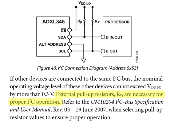
Hi, I have problems reading the contents of the registers from a sensor conected to the I2C bus in the C2000 Peripheral Explorer Kit. The sensor is the ADXL345, an accelerometer that stores the readings in 8-bit registers (2 registers per reading, one with higher byte and the other with lower byte). The configuration of the sensor should be correct because the debugger goes on step by step.
The program works, but the values read make no sense, because I am obtaining always the same value from those registers, no matter which register I am reading or the position of the sensor. Please find attached the code, I really don't know what is it that I'm doing wrong.
Also, is there anyway to monitor the state of the signals SCL and SDA to understand better if something is being done wrong?
Thank you very much.
//###########################################################################
//
// FILE:	ADXL345.c
//
// TITLE:	DSP28335 I2C test
//          Accelerometer ADXL345 connected to GPIO33 (SCL) and GPIO32(SDA)
//			LED LD1 as life indicator 100 ms toggle
//
//###########################################################################

#include "DSP2833x_Device.h"

// Define register addresses
#define ACCEL 0x53			// slave address
#define ACCEL_WRITE 0xA6	// slave address for writing
#define ACCEL_READ 0xA7		// slave address for reading
#define POWER_CTL 0x2D		// POWER_CTL register at sensor
#define DATAX0 0x32			// LS byte for X measurement
#define DATAX1 0x33			// MS byte for X measurement
#define DATAY0 0x34			// LS byte for Y measurement
#define DATAY1 0x35			// MS byte for Y measurement
#define DATAZ0 0x36			// LS byte for Z measurement
#define DATAZ1 0x37			// MS byte for Z measurement

// external function prototypes
extern void InitSysCtrl(void);
extern void InitPieCtrl(void);
extern void InitPieVectTable(void);

// Prototype statements for functions found within this file.
void Gpio_select(void);
void I2CA_Init(void);

int xaccel = 0;
int yaccel;
int zaccel;

//###########################################################################
//						main code
//###########################################################################
void main(void)
{

	InitSysCtrl();	// Basic Core Init from DSP2833x_SysCtrl.c

	EALLOW;
   	SysCtrlRegs.WDCR= 0x00AF;	// Re-enable the watchdog
   	EDIS;			// 0x00AF  to NOT disable the Watchdog, Prescaler = 64

	DINT;				// Disable all interrupts

	Gpio_select();

	//	Initialize I2C
	I2CA_Init();

	// Initialize and configure ADXL345
	I2caRegs.I2CCNT = 3;					//Send 3 bytes
	I2caRegs.I2CDXR = ACCEL_WRITE;			//Select POWER_CTL register in sensor
	I2caRegs.I2CMDR.all = 0x6E20;			//Generate start and stop, master transmitter
	while(I2caRegs.I2CSTR.bit.XRDY == 0);	// wait until first byte is out
	I2caRegs.I2CDXR = POWER_CTL;			//Select POWER_CTL register in sensor
	while(I2caRegs.I2CSTR.bit.XRDY == 0);	// wait until second byte is out
	I2caRegs.I2CDXR = 0x08;					//Activate measurement mode in sensor
	while(I2caRegs.I2CSTR.bit.SCD == 0);	// wait for STOP condition
	I2caRegs.I2CSTR.bit.SCD = 1;

	InitPieCtrl();		// basic setup of PIE table; from DSP2833x_PieCtrl.c
	InitPieVectTable();	// default ISR's in PIE

	InitCpuTimers();	// basic setup CPU Timer0, 1 and 2

	PieCtrlRegs.PIEIER1.bit.INTx7 = 1;

	IER |=1;

	EINT;
	ERTM;

	EALLOW;
	SysCtrlRegs.WDKEY = 0x55;	// service WD #1
	EDIS;

	//Read acceleration on X axis
	//Higher 8 bits (DATAX1 register)
	I2caRegs.I2CCNT	= 2;					//Write 1 byte (register address)
	I2caRegs.I2CDXR = ACCEL_WRITE;			//Select higher byte register in sensor
	I2caRegs.I2CMDR.all = 0x6E20;			//Generate start and stop, master transmitter
	while(I2caRegs.I2CSTR.bit.XRDY == 0);	// wait until first byte is out
	I2caRegs.I2CDXR = DATAX1;				//Select higher byte register in sensor
	while(I2caRegs.I2CSTR.bit.SCD == 0);	// wait for STOP condition
	I2caRegs.I2CSTR.bit.SCD = 1;

	I2caRegs.I2CCNT	= 1;					//Write 1 byte (register address)
	I2caRegs.I2CDXR = ACCEL_READ;			//Select higher byte register in sensor
	I2caRegs.I2CMDR.all = 0x6620;			//Generate start but not stop, master transmitter
	while(I2caRegs.I2CSTR.bit.XRDY == 0);	// wait until first byte is out

	while(I2caRegs.I2CSTR.bit.ARDY == 0);	// wait for access ready condition
	I2caRegs.I2CCNT	= 1;					//Read 1 byte (register address)
	I2caRegs.I2CMDR.all = 0xEC20;			//Generate stop but not start, master receiver, generate NACK
	while(I2caRegs.I2CSTR.bit.RRDY == 0);	// wait for byte
	xaccel = I2caRegs.I2CDRR<<8;			// read upper 8 Bit (integers)

	//Lower 8 bits (DATAX0 register)
	I2caRegs.I2CCNT	= 2;					//Write 1 byte (register address)
	I2caRegs.I2CDXR = ACCEL_WRITE;			//Select higher byte register in sensor
	I2caRegs.I2CMDR.all = 0x6E20;			//Generate start and stop, master transmitter
	while(I2caRegs.I2CSTR.bit.XRDY == 0);	// wait until first byte is out
	I2caRegs.I2CDXR = DATAX0;				//Select higher byte register in sensor
	while(I2caRegs.I2CSTR.bit.SCD == 0);	// wait for STOP condition
	I2caRegs.I2CSTR.bit.SCD = 1;

	I2caRegs.I2CCNT	= 1;					//Write 1 byte (register address)
	I2caRegs.I2CDXR = ACCEL_READ;			//Select higher byte register in sensor
	I2caRegs.I2CMDR.all = 0x6620;			//Generate start but not stop, master transmitter
	while(I2caRegs.I2CSTR.bit.XRDY == 0);	// wait until first byte is out

	while(I2caRegs.I2CSTR.bit.ARDY == 0);	// wait for access ready condition
	I2caRegs.I2CCNT	= 1;					//Read 1 byte (register address)
	I2caRegs.I2CMDR.all = 0xEC20;			//Generate stop but not start, master receiver, generate NACK
	while(I2caRegs.I2CSTR.bit.RRDY == 0);	// wait for byte
	xaccel += I2caRegs.I2CDRR;				// read lower 8 Bit (integers)

	EALLOW;
	SysCtrlRegs.WDKEY = 0xAA;	// service WD #2
	EDIS;

}

void Gpio_select(void)
{
	EALLOW;
	GpioCtrlRegs.GPAMUX1.all = 0;			// GPIO15 ... GPIO0 = General Puropse I/O
	GpioCtrlRegs.GPAMUX2.all = 0;			// GPIO31 ... GPIO16 = General Purpose I/O

	GpioCtrlRegs.GPBMUX1.all = 0;			// GPIO47 ... GPIO32 = General Purpose I/O
	GpioCtrlRegs.GPBMUX1.bit.GPIO32 = 1;	// GPIO32 = I2C - SDA
	GpioCtrlRegs.GPBMUX1.bit.GPIO33 = 1;	// GPIO33 = I2C - SCL

	GpioCtrlRegs.GPBPUD.bit.GPIO32 = 0;    // Enable pull-up for GPIO32 (SDAA)
	GpioCtrlRegs.GPBPUD.bit.GPIO33 = 0;	   // Enable pull-up for GPIO33 (SCLA)

	GpioCtrlRegs.GPBQSEL1.bit.GPIO32 = 3;  		// Asynch input GPIO32 (SDAA)
	GpioCtrlRegs.GPBQSEL1.bit.GPIO33 = 3;	// Asynch input GPIO33 (SCLA)

	GpioCtrlRegs.GPBMUX2.all = 0;			// GPIO63 ... GPIO48 = General Purpose I/O

	GpioCtrlRegs.GPCMUX1.all = 0;			// GPIO79 ... GPIO64 = General Purpose I/O
	GpioCtrlRegs.GPCMUX2.all = 0;			// GPIO87 ... GPIO80 = General Purpose I/O


	GpioCtrlRegs.GPADIR.all = 0;			// GPIO0 to 31 as inputs
	GpioCtrlRegs.GPADIR.bit.GPIO9 = 1;		// GPIO9 = LED LD1
	GpioCtrlRegs.GPADIR.bit.GPIO11 = 1;		// GpIO11 = LED LD2

	GpioCtrlRegs.GPBDIR.all = 0;			// GPIO63-32 as inputs
	GpioCtrlRegs.GPBDIR.bit.GPIO34 = 1;		// peripheral explorer: LED LD3 at GPIO34
	GpioCtrlRegs.GPBDIR.bit.GPIO49 = 1; 	// peripheral explorer: LED LD4 at GPIO49

	GpioCtrlRegs.GPCDIR.all = 0;			// GPIO87-64 as inputs
	EDIS;
}

void I2CA_Init(void)
{

	I2caRegs.I2CMDR.bit.IRS = 0;	// Reset the I2C module
	I2caRegs.I2CSAR = ACCEL;			//Select write address for sensor
	// I2C Prescale Register
	I2caRegs.I2CPSC.all = 14;		// Internal I2C module clock = SYSCLK/(PSC +1)
								    // = 10 MHz

//	I2caRegs.I2CCLKL = 95;			// Tmaster = (PSC +1)[ICCL + 5 + ICCH + 5] / 150MHz
//	I2caRegs.I2CCLKH = 95;			// Tmaster =  15 [ICCL + ICCH + 10] / 150 MHz
									// d = 5  for IPSC >1

									// for I2C 50 kHz:
									// Tmaster = 20 µs * 150 MHz / 15 = 200 = (ICCL + ICCH +10)
									// ICCL + ICCH = 190
									// ICCL = ICH = 190/2 = 95

	I2caRegs.I2CCLKL = 45;
	I2caRegs.I2CCLKH = 45;			// for I2C 100 kHz:
									// Tmaster = 10 µs *150 MHz / 15 = 100 = (ICCL + ICCH + 10)
									// ICCL + ICCH = 90
									// ICCL = ICH = 90/2 = 45

	I2caRegs.I2CMDR.bit.IRS = 1;	// Take I2C out of reset
}

//===========================================================================
// End of SourceCode.
//===========================================================================