This thread has been locked.

If you have a related question, please click the "Ask a related question" button in the top right corner. The newly created question will be automatically linked to this question.

Sensored FOC of PMSM - Motor stalling at level 4

Hi,

    I am working on the Sensored FOC of PMSM on TI's TMDSHVMTRPFCKIT. I am using the example program provided by TI for running a PMS Motor provided by TI. I am successful in incrementally building upto the 3rd BUILDLEVEL of the software. However, at BUILDLEVEL 4, when lsw is set to 2 ( ie, when the speed is also controlled in a closed loop ) and the input voltage to the kit from a variac goes above 100 V, the motor initally jerks and then stops rotating.

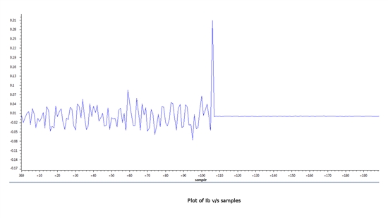
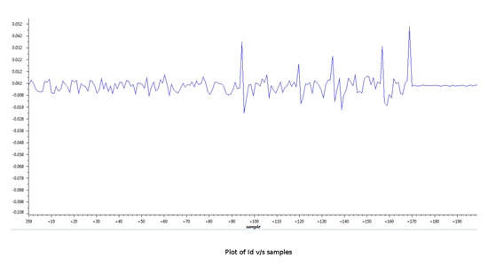
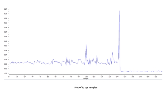
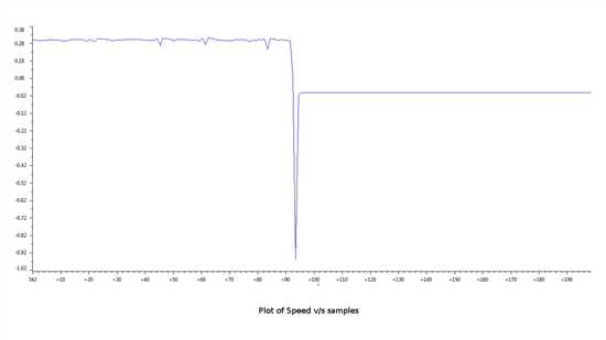
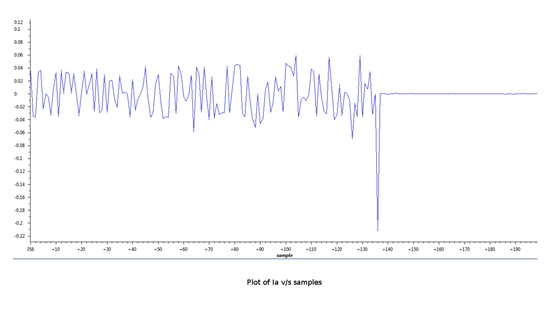
    I am attaching real time plots of currents Ia, Ib, Id and Iq, of the Rawtheta value computed from QEP feedback as well as the plot of the Speed, which were obtained during the run time. Kindly analyse the plots and give me a solution to overcome this issue.
  • Hi Anil,

    I am able to repeat this test without any issues.

    Are you ensuring that the speed estimate from QEP and ref speed are in same polarity, I mean, same direction of rotation. From your speed plot, it appears that QEP is sensing speed in reverse direction. I suggest swapping any two wires to motor and trying again.

    rgds,

    ramesh

  • Hi Ramesh,

            I have uploaded the plots of the variables after setting lsw = 2. ie, the QEP feedback is already being used for calculating the required outputs. The negative peak that you find in the speed plot is when the input voltage from my variac crossed 100V. So, swapping wires is not a solution right? Please correct me if I'm wrong anywhere.

    Thanks and regards, 

    Aravind

  • Also, can you please share an ideal plot of the QEP feedback? 

  • My comment was based on the angle plot, it shows a negative slope. But then the speed plot is showing positive. If the angle slope is negative, then speed estimate should be negative. (speed = differential of angle). I don't how you got it.

    I would check to ensure that jumper J4 in M5 block is not populated.  Then, if you are able to successfully run in lsw=2, and that the problem is only after 100V ac input, I have no clue. We cant reproduce it nor we received such complaints.

    Otherwise, review the code, and plot rg1.Out and qep1.Electheta. If they are of opposite slope, then you need to swap the wires.

    rgds,

    ramesh

  • Dear Mr. Aravind

    I also work on the same development board as you are. If it is not bothering you, now i have some problems on build 3. 

    I have some difficulties regarding rotor position calibration. Based on the explanation from the ControlSuite, if we want to lock the rotor into d-axis, we can set the Iq=0 and Id=some constant value then the rotor will move a little to align with the d-axis. This step happened when I did this step, but sometimes not. I guess this is depend on the first rotor position (if it is not, please correct me). Now, I only able to rotate the motor in 100rpm. The motor will stalled if the speed is over than 100rpm.

    The problems :

    1. does it happened because of the position not calibrated?

    2. how to know the rotor position has already align with the d-axis from the code/watch windows?it said on the application note that when the first index signal is detected by the QEP, the QPOSILAT latches the angle offset in between initial rotor position and encoder index. How to get the offset angle?

    3. on the application note also writen CALIBRATION ANGLE= OFFSET ANGLE +- n.LINE ENCODER. what is n.LINE ENCODER? on the code from ControlSuite, the default calibration angle value is 1000 for 2500 PPR encoder. do i need to change the calibration angle value each time the program is restart?

    Can you share some knowledge how to calibrate the position of the rotor?

    Thank you.