This thread has been locked.
If you have a related question, please click the "Ask a related question" button in the top right corner. The newly created question will be automatically linked to this question.
Hi,
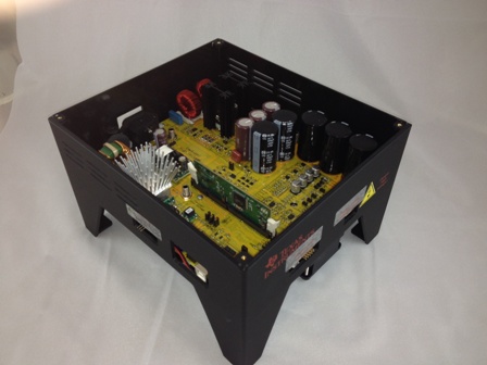
I am working on TMDSHVMTRPFCKIT motor control kit along with the PMS Motor provided. I am using the sample code, Sensored FOC of PMSM, provided by TI to run the motor.
At build level 4 ( with the PI modules for Currents and Speed active), when the AC voltage input to the motor goes above 100V, I am facing two situations - either the motor stops running, showing off all the red LEDs in the board or the motor starts rotating in the opposite direction with very high speed and no control at all.
Whats going behind? Can anyone please help me out of this ?
Hi Aravind,
I am going to move your post to the InstaSPIN forum. They should be able to better assist.
If you are able to run the motor fine in BUILD_LEVEL3 at these voltage levels, then it should run fine in LEVEL4 as well. If not, I would suspect that the QEP signals are some how corrupted to throw the control off. From level 3 to 4, the following changes are made
- angle information from QEP replaces the forced angle for PARK transform within the loop.
- speed loop provides Iq loop reference.
Hope you figure it out from here.
rgds,
ramesh
Hi Ramesh,
Thanks for the quick response. I was able to work at these voltages, and even above, in build Level 3.
By saying that the QEP signals are corrupted, what do you mean? Will it be possible for you to suggest some troubleshooting methods for the same?
1. Change the resistors R20-R22 to 47K (from 4K7).
2. Run in build 3 and verify the signals at 3.3V side. If they are good, try build 4.
3. If build 4 gives problems still, then check QEP signals again for any noise pick up or stuff like that.
rgds,
ramesh
Hi Ramesh,
Thanks for your concern. However, I have a very basic doubt about this. For a system working well when the input voltage is below 100V AC, what sort of corruption can enter into the QEP feedback when I raise the input voltage ? If it were an error with the feedback system, then should not it be present at all voltage levels ?
The only suspect link is QEP. May be the GND jitters are too bad or stuff like that happening at higher voltage.
If it were the case, then it should be a hardware design issue right ? And then problem should be common. I have extensively searched this forum and I have hardly come across such a situation. What is the support that TI provides in such cases? I am no good at soldering SMD components and hence replacing the resistors is out of the options. There is no other local support I can take for soldering the components also. Kindly help.