This thread has been locked.

If you have a related question, please click the "Ask a related question" button in the top right corner. The newly created question will be automatically linked to this question.

Inductance identification problem

Other Parts Discussed in Thread: DRV8301

Dear Sir /Madam,

I have problems during the inductance identification in Lab 2a. The motor does not spin and sometimes overcurrent protection flag of the mosfets driver is raised (custom HW)

Resistance and Rated Flux are identified correctly.

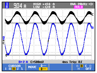
I have ploted  phase currents during the RoverL step in order to validate both power and measurement circuits. The figure shows  the current in phase U (blue) and Current Phase A after the current sense circuit and filters during  the RoverL steps. It seems to be OK. (Phase V and W are similars)

The identification runs OK until the inductance identification process. The motors stops suddenly and starts to vibrate (sometimes the short circuit protection of the drivers is raised) no matter the current used.

I have also used the DRV8301 evaluation boards to make this identification and it is correctly performed.

// DELTA_ME080AS104
#define USER_MOTOR_TYPE MOTOR_Type_Pm
#define USER_MOTOR_NUM_POLE_PAIRS (2)
#define USER_MOTOR_Rr (NULL)
#define USER_MOTOR_Rs (0.009204548)
#define USER_MOTOR_Ls_d (0.00004952461)
#define USER_MOTOR_Ls_q (0.00004952461)
#define USER_MOTOR_RATED_FLUX (0.05395144)
#define USER_MOTOR_MAGNETIZING_CURRENT (NULL)
#define USER_MOTOR_RES_EST_CURRENT (7.0)
#define USER_MOTOR_IND_EST_CURRENT (-7.0)
#define USER_MOTOR_MAX_CURRENT (10.0)
#define USER_MOTOR_FLUX_EST_FREQ_Hz (13.0)
#define USER_MOTOR_MAX_SPEED_KRPM (3.0)
#define USER_MOTOR_MAX_ACCEL (32.0) // Maximum acceleration (KRPM/s)

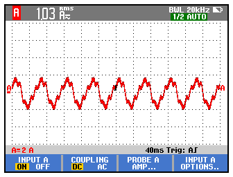
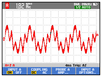
If we use the parameters identified with DRV8301 with our own HW and runs the Lab3B it works OK. We only have problems when the inductance has to be identified. Current Waveforms are not perfects, but it spins softly. The following image shows the Phase U currents when the motor is running at 500rpm and 2000rpm

I have read in previous post that lab2c should be used in case of low inductances, but in this case R/L = 185 (<< 2000)

I have also tested our HW with other motors (with higher L and R) and the identifications is performed OK. This higher resistance probably filters the signal allowing the L identification.

What can cause the motor to vibrate during the inductance identification step?

  • "I have also used the DRV8301 evaluation boards to make this identification and it is correctly performed."
    What does this mean? What HW are you using where you are having issues?

    #define USER_MOTOR_RES_EST_CURRENT (7.0)
    #define USER_MOTOR_IND_EST_CURRENT (-7.0)

    these values are very high for a 10A max current motor. I recommend starting at 1.0 and only increasing if the motor doesn't start spinning during the RampUp state.

    Is this really only a 3 KRPM / 100 Hz machine? It's parameters are pretty unusual for such a machine with an extremely low Rs value.

    When you start motor ID and RoverL is performed what is the value in ctrl.RoverL (F2802x) or controller_ojb* RoverL (F2806x) ?
  • Dear Chris,

    What HW are you using where you are having issues?

    I am having problems with my own HW. Previously DRV8301 evb was used with correct results.

    #define USER_MOTOR_RES_EST_CURRENT (7.0)

    #define USER_MOTOR_IND_EST_CURRENT (-7.0)

    these values are very high for a 10A max current motor. I recommend starting at 1.0 and only increasing if the motor doesn't start spinning during the RampUp state.

    Motor nominal current is 44A (7A is 15%) 10A limitation was due to current sense resistors. Our HW is designed to measure up to 150A. When these problems appeared we thought that we had a poor resolution so we changed the current sense resistors in order to measure up to 10A. From previous test with DRV8301 evaluation board we saw that no more than 10A  (L and R currents were 6A) were needed to make the identification. Obviously these resistors should be changed for normal working (with load). We have now nearly the same measurement circuit as High voltage evaluation board.

    Vo = 1.65-8.2965Vsense.

    A RC filter has been included at the output of each current measurement operational. This filter has a cut off frequency about 3.7KHz

    Is this really only a 3 KRPM / 100 Hz machine? It's parameters are pretty unusual for such a machine with an extremely low Rs value

    Please, find attached the motor datasheet. Resistance and Inductance values are not defined in the datasheet. We have only the values identified with instaspin and DRV8301 evb.

    When you start motor ID and RoverL is performed what is the value in ctrl.RoverL (F2802x) or controller_ojb* RoverL (F2806x) ?

    543.9399

    Thank you in  advance,

    Borja

    motorware_variables_ME080AS104.xlsx

    ME080AS104.pdf

  • If you have the DRV8301 EVM I suggest using it first to perform a successful ID with 2a or 2b. Let's get good known values and performance first for this motor. If your HW isn't able to replicate there is likely something incorrect in your HW sense circuits.

    I would use (4.0) and (-2.0) for RES_EST and IND_EST settings to start. You only need to increase the (4.0) if the motor doesn't start-up during Motor ID. Don't increase the IND_EST.

    also set
    #define USER_R_OVER_L_EST_FREQ_Hz (100)


    this motor has a very large short circuit current, so the current ripple is going to be pretty bad. it may help to increase the PWM frequency up to 30 or 45 KHz, with the current at an effective 15 KHz.
  • Dear Chris,
    I have previously run lab 2a 3a, 3b and inertia related labs (5c, 12a, 12b and 13a) with drv8301 without problems. The values given before, were the value identified with this evaluation board.

    I can not replicate lab 2a with my own hw. Resistance and rated flux value were quite similar to the one identified witn the evb, but i do not know what happens in rated flux to inductance step that makes the motor start to vibrate.

    I will try with 30khz pwm. This is the máximum value allowed by mosfets driver.

    Thanks

    Borja
  • did you update the dead-time settings for your board? I assume you aren't using DRV8301 anymore, or are you?
  • Chris,
    Deadtime are the same as drv8301. MOSFET driver inserts a default 400us deadtime. Can the deadtime be set to 0 (driver will imsert it)? Labs sw define it as 1.0 x systemclock
    The driver needs a 0 to trigger high side mosfets and 1 to trigger low side mosfets. This high side pwm signal inversión has been made by hw with logical gates, but i have doubts about the effect of this deadtime
    Thank you
    Borja
  • I suppose you can set the value in hal.h to 0.

    do you have a current probe? I think there is something abnormal with your current sense.
  • Yes i have. The plots i have posted has been captured using a current probes. Phase currents during RoverL step are sinusoidals so i suppose currents signal is generated and measured correctly. Phase currents during lab3 are not perfects, bit they could be worse.
    What should i expect during inductance identification?
  • your first image, is it at the frequency you set in user.h for ROVERL? correct magnitude of 1/2 RES_EST_CURRENT?
  • Dear Chris,

    I have followed your recomendations about USER_MOTOR_RES_EST_CURRENT  and USER_MOTOR_IND_EST_CURRENT. Reducing the second parameter the inductance value is now estimated correctly (or at least values are similar indentifiend with evb)

    Values estimated with Evaluation Board

    #define USER_MOTOR_Rs                   (0.009204548)

    #define USER_MOTOR_Ls_d                 (0.00004952461)

    #define USER_MOTOR_Ls_q                 (0.00004952461)

    #define USER_MOTOR_RATED_FLUX           (0.05395144)

    Values estimated with custom HW

    #define USER_MOTOR_Rs                   (0.007345113)

    #define USER_MOTOR_Ls_d                 (0.00002007102)

    #define USER_MOTOR_Ls_q                 (0.00002007102)

    #define USER_MOTOR_RATED_FLUX           (0.05209995)

    I have also tried to increase the PWM frequency from 15KHz to 30KHz,

    #define USER_PWM_FREQ_kHz                (30.0)

    #define USER_NUM_PWM_TICKS_PER_ISR_TICK        (2)

    your first image, is it at the frequency you set in user.h for ROVERL? correct magnitude of 1/2 RES_EST_CURRENT?

    I have plotted the phase currents during RoverL step;

    RES_EST_CURRENT = 4A


    RES_EST_CURRENT = 5.


    RES_EST_CURRENT  = 6A


    The waveform for the three cases is sinusoidal with a frequency of 100Hz, but the current seems to be nearly the double I expected. The same happens during Rs recalibration step. So, probably there is something wrong in the measurement circuit

    The current measurement circuit is the one shown in the following figure

    So 

    #define USER_IQ_FULL_SCALE_CURRENT_A          (46.0)   // 

    #define USER_ADC_FULL_SCALE_CURRENT_A        (90.00)     // current scaling

    If voltage is measured at filter output (Vadc) it reflects a smaller current than the measured at motor phases but already bigger than expected.

    Previously you said that "this motor has a very large short circuit current, so the current ripple is going to be pretty bad". How does it affect to the measurement circuit?

    Thank you in advance

    Borja


  • "So, probably there is something wrong in the measurement circuit"
    - I agree, seeing the Rs and Ls values not identified the same and that the current magnitude is ~double.


    "Previously you said that "this motor has a very large short circuit current, so the current ripple is going to be pretty bad". How does it affect to the measurement circuit?"
    - current ripple makes it more challenging to get a valid average current measurement as the current doesn't decay linearly. This is always a challenge for doing current control (FOC) on a low inductance motor