Hi guys,
I just bought the DRV8312-69M-KIT .It works well with the code from motorware. According to these posts , and
and
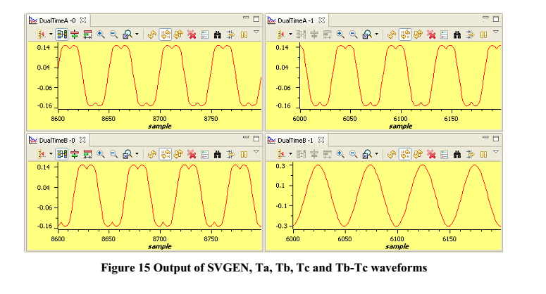
 , I think that the code (C:\ti\controlSUITE\development_kits\DRV8312-C2-KIT_v128\PM_Sensorless) could work well,if I set active as F2806x_RAM. I build level 1 , the ccs is ok there are no bugs or errors.But the result I read from the dacs are not the same as the guidence(C:\ti\controlSUITE\development_kits\DRV8312-C2-KIT_v128\PM_Sensorless\~Docs).
These are the results from the DAC1 and DAC3(Ta and Tb-Tc waveforms)
#if (BUILDLEVEL==LEVEL1)
// ------------------------------------------------------------------------------
// Connect inputs of the RMP module and call the ramp control macro
// ------------------------------------------------------------------------------
rc1.TargetValue = SpeedRef;
RC_MACRO(rc1)
// ------------------------------------------------------------------------------
// Connect inputs of the RAMP GEN module and call the ramp generator macro
// ------------------------------------------------------------------------------
rg1.Freq = rc1.SetpointValue;
RG_MACRO(rg1)
// ------------------------------------------------------------------------------
// Connect inputs of the INV_PARK module and call the inverse park trans. macro
// ------------------------------------------------------------------------------
ipark1.Ds = VdTesting;
ipark1.Qs = VqTesting;
ipark1.Sine=_IQsinPU(rg1.Out);
ipark1.Cosine=_IQcosPU(rg1.Out);
IPARK_MACRO(ipark1)
// ------------------------------------------------------------------------------
// Connect inputs of the SVGEN_DQ module and call the space-vector gen. macro
// ------------------------------------------------------------------------------
svgen_dq1.Ualpha = ipark1.Alpha;
svgen_dq1.Ubeta = ipark1.Beta;
SVGEN_MACRO(svgen_dq1)
// ------------------------------------------------------------------------------
// Connect inputs of the PWM_DRV module and call the PWM signal generation macro
// ------------------------------------------------------------------------------
pwm1.MfuncC1 = _IQtoQ15(svgen_dq1.Ta);
pwm1.MfuncC2 = _IQtoQ15(svgen_dq1.Tb);
pwm1.MfuncC3 = _IQtoQ15(svgen_dq1.Tc);
PWM_MACRO(pwm1) // Calculate the new PWM compare values
EPwm1Regs.CMPA.half.CMPA=pwm1.PWM1out; // PWM 1A - PhaseA
EPwm2Regs.CMPA.half.CMPA=pwm1.PWM2out; // PWM 2A - PhaseB
EPwm3Regs.CMPA.half.CMPA=pwm1.PWM3out; // PWM 3A - PhaseC
// ------------------------------------------------------------------------------
// Connect inputs of the PWMDAC module
// ------------------------------------------------------------------------------
PwmDacCh1 = _IQtoQ15(svgen_dq1.Ta);
PwmDacCh2 = _IQtoQ15(svgen_dq1.Tb);
PwmDacCh3 = _IQtoQ15(svgen_dq1.Tb-svgen_dq1.Tc);
// ------------------------------------------------------------------------------
// Connect inputs of the DATALOG module
// ------------------------------------------------------------------------------
DlogCh1 = _IQtoQ15(svgen_dq1.Ta);
DlogCh2 = _IQtoQ15(svgen_dq1.Tb);
DlogCh3 = _IQtoQ15(svgen_dq1.Tc);
DlogCh4 = _IQtoQ15(svgen_dq1.Tb-svgen_dq1.Tc);
#endif // (BUILDLEVEL==LEVEL1)
I don't know why does the wave like this. Thanks a lot!


