This thread has been locked.

If you have a related question, please click the "Ask a related question" button in the top right corner. The newly created question will be automatically linked to this question.

Program goes to Default ISR (ILLIGAL_ISR)

Other Parts Discussed in Thread: CONTROLSUITE

Hello,

I have used the Example_28027_Flash to program from flash and modified it for UP_DOWN PWM. I am working on C2000 launchpad with F28027 controller on it.

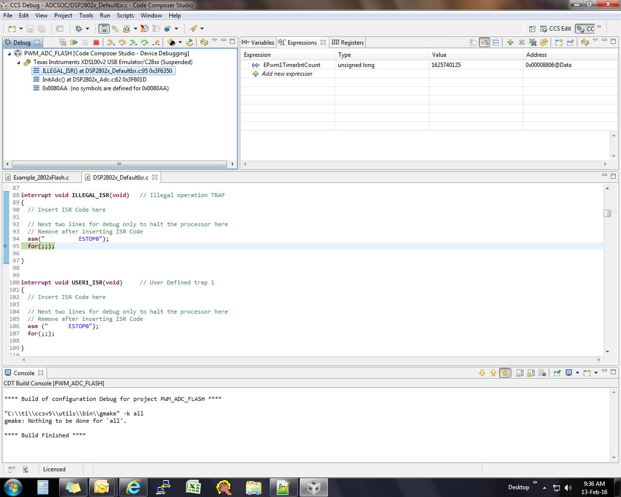
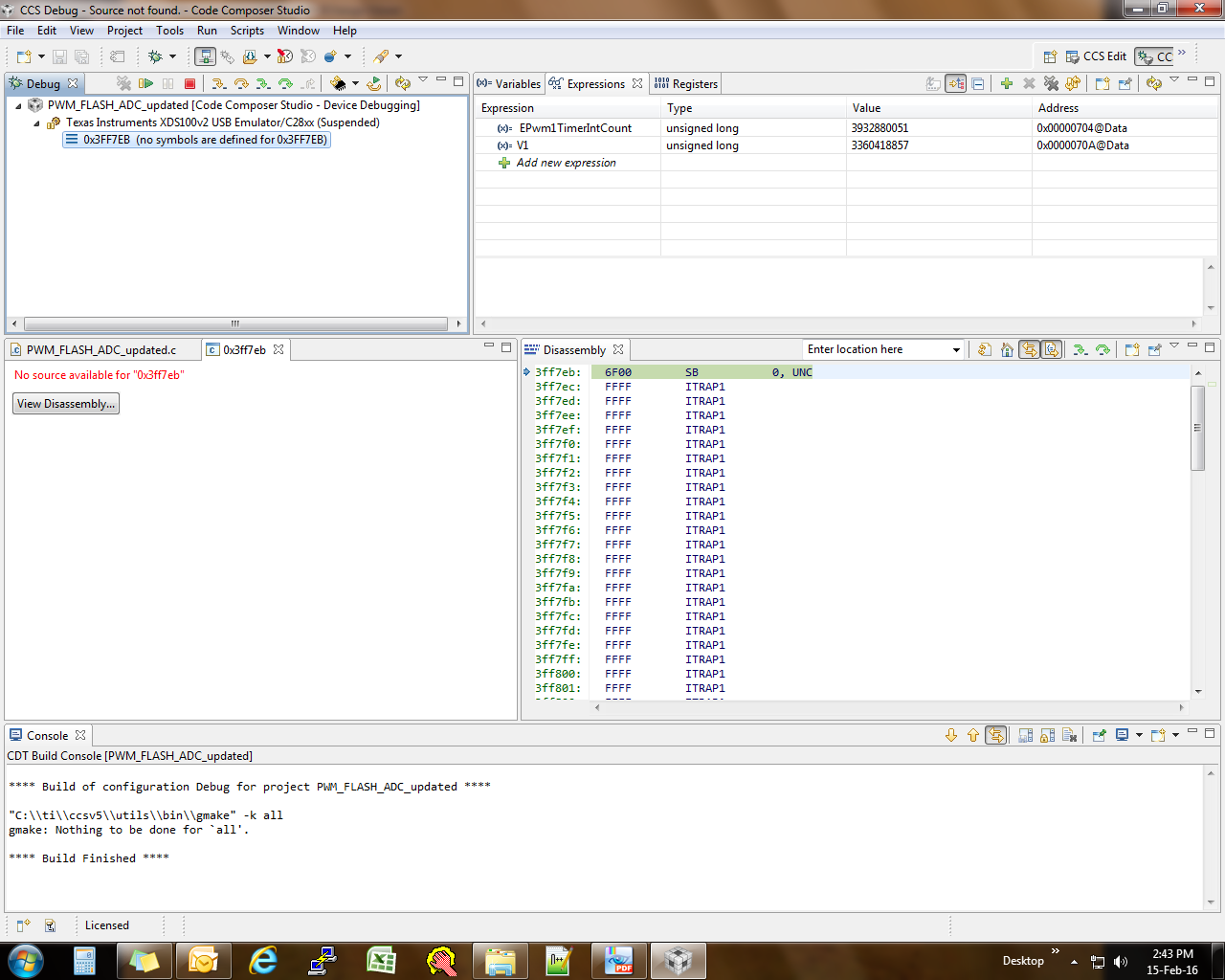
When I buid it only with PWM code it works fine. But when I include ADC code into it, during debug it goes into Default ISR loop.

I am attaching my code for reference.

Please share your view.PWM_ADC_FLASH.zip

  • Hi,

    I would recommend you to check these posts:

    e2e.ti.com/.../256102.aspx
    e2e.ti.com/.../143012.aspx
    e2e.ti.com/.../104980.aspx
    e2e.ti.com/.../945759.aspx
    I'm not sure that it will be useful to you exactly. But maybe...

    Also you can comment your code inside ADC ISR and try to check.

    Regards,
    Aditya
  • Anupsingh,

    The most common cause of an illegal ISR is that you've tried to access an unintended memory location.  In your case it's probably happening because you're indexing beyond the range of an array (actually two arrays).  Your voltage arrays are declared as:

    Uint16 Voltage1[10];
    Uint16 Voltage2[10];

    In your ISR you have (simplified):

    Voltage1[ConversionCount] = AdcResult.ADCRESULT1;
    Voltage2[ConversionCount] = AdcResult.ADCRESULT2;

    // If 25 conversions have been logged, start over
    if(ConversionCount == 29)
    {
    ConversionCount = 0;
    }

     else ConversionCount++;

    Leaving aside the inconsistency between the comment and the equality on the next line, think about what memory is going to be accessed when ConversionCount is incremented to 10 or greater.

    Regards,

    Richard

  • Hello Richard,

    Thank you for your reply.

    I have modified the code and reduced the value of convesion count. Even though I reduce it to less than 9, it doesn't work.

    Even I tried to comment adc_ISR code, then also it goes into same loop. But when I load only EPWM code it works well after inserting ADC code this happens.

    Is there any issue with ADC code.

    interrupt void  adc_isr(void)
    {
    
    
    Voltage1[ConversionCount] = AdcResult.ADCRESULT1;  //discard ADCRESULT0 as part of the workaround to the 1st sample errata for rev0
     // Voltage2[ConversionCount] = AdcResult.ADCRESULT2;
      sum += Voltage1[ConversionCount];
      // If 6 conversions have been logged, start over
      if(ConversionCount == 5)
     {
    	  V1 = sum/ConversionCount;
    	  V2 = (V1 * 3.3)/(4096) ;
    	  sum=0;
          ConversionCount = 0;
      }
    
      else ConversionCount++;
    
      AdcRegs.ADCINTFLGCLR.bit.ADCINT1 = 1;		//Clear ADCINT1 flag reinitialize for next SOC
      PieCtrlRegs.PIEACK.all = PIEACK_GROUP1;   // Acknowledge interrupt to PIE
      return;
    }
    
    void ConfigADC()
    {
    //Note: Channel ADCINA4  will be double sampled to workaround the ADC 1st sample issue for rev0 silicon errata
    
    	EALLOW;
    		AdcRegs.ADCCTL1.bit.INTPULSEPOS	= 1;	//ADCINT1 trips after AdcResults latch
    		AdcRegs.INTSEL1N2.bit.INT1E     = 1;	//Enabled ADCINT1
    		AdcRegs.INTSEL1N2.bit.INT1CONT  = 0;	//Disable ADCINT1 Continuous mode
    		AdcRegs.INTSEL1N2.bit.INT1SEL	= 2;	//setup EOC2 to trigger ADCINT1 to fire
    		AdcRegs.ADCSOC0CTL.bit.CHSEL 	= 4;	//set SOC0 channel select to ADCINA4
    		AdcRegs.ADCSOC1CTL.bit.CHSEL 	= 4;	//set SOC1 channel select to ADCINA4
    		AdcRegs.ADCSOC2CTL.bit.CHSEL 	= 2;	//set SOC1 channel select to ADCINA2
    		AdcRegs.ADCSOC0CTL.bit.TRIGSEL 	= 7;	//set SOC0 start trigger on EPWM1A, due to round-robin SOC0 converts first then SOC1
    		AdcRegs.ADCSOC1CTL.bit.TRIGSEL 	= 7;	//set SOC1 start trigger on EPWM1A, due to round-robin SOC0 converts first then SOC1
    		AdcRegs.ADCSOC2CTL.bit.TRIGSEL 	= 7;	//set SOC2 start trigger on EPWM1A, due to round-robin SOC0 converts first then SOC1, then SOC2
    		AdcRegs.ADCSOC0CTL.bit.ACQPS 	= 9;	//set SOC0 S/H Window to 7 ADC Clock Cycles, (6 ACQPS plus 1)
    		AdcRegs.ADCSOC1CTL.bit.ACQPS 	= 9;	//set SOC1 S/H Window to 7 ADC Clock Cycles, (6 ACQPS plus 1)
    		AdcRegs.ADCSOC2CTL.bit.ACQPS 	= 9;	//set SOC2 S/H Window to 7 ADC Clock Cycles, (6 ACQPS plus 1)
    		EDIS;
    
    	// Assumes ePWM1 clock is already enabled in InitSysCtrl();
    	   EPwm2Regs.ETSEL.bit.SOCAEN	= 1;		// Enable SOC on A group
    	   EPwm2Regs.ETSEL.bit.SOCASEL	= 4;		// Select SOC from from CPMA on up count
    	   EPwm2Regs.ETPS.bit.SOCAPRD 	= 1;		// Generate pulse on 1st event
    	   EPwm2Regs.CMPA.half.CMPA	    = duty_cycle;	// Set compare A value
    	   EPwm2Regs.TBPRD 				= period;	// Set period for ePWM1
    	   EPwm2Regs.TBCTL.bit.CTRMODE 	= 0;		// count up and start
    
    }

  • Hi Anup,

    Could you please upgrade your controlSUIT version to latest and try to check the same?

    I have noticed that you are using v129 as per your attached project code. It is old version of device support folder.

    regards

    Aditya 

  • Hi,

    According to the screenshot (call stack) your problem might be related to the InitAdc function. Could you please try to comment out that as well, and also the part of the ConfigADC that deals with the ADC.

    BR,

    Janos

  • Hello Aditya,

    Thank you for your suggestions.

    Tried it but not giving a useful result. Attaching a screen shot.

    Though I found one code by Gautam, on one of the threads which integrates ADC and EPWM, trying to understand it..hopw it will work in my system.

    //#############################################################################
    // Code: ADC and PWM Integrated for TMS320FF28027
    // Name: Gautam G. Iyer
    // Location: Bangalore, India
    //#############################################################################
    
    #include "DSP28x_Project.h"     // Device Headerfile and Examples Include File
    
    #include "f2802x_common/include/adc.h"
    #include "f2802x_common/include/clk.h"
    #include "f2802x_common/include/flash.h"
    #include "f2802x_common/include/gpio.h"
    #include "f2802x_common/include/pie.h"
    #include "f2802x_common/include/pll.h"
    #include "f2802x_common/include/pwm.h"
    #include "f2802x_common/include/wdog.h"
    
    // Prototype statements for functions found within this file.
    #define PWM1_TIMER_TBPRD   0x00C8			//TBPRD = 200 == 150Khz
    
    void InitEPwm1(void);
    // Global variables used in this example:
    uint16_t LoopCount;
    uint16_t ConversionCount;
    uint16_t V1, V2, V3;
    uint16_t V4, V5, V6;
    
    ADC_Handle myAdc;
    CLK_Handle myClk;
    FLASH_Handle myFlash;
    GPIO_Handle myGpio;
    PIE_Handle myPie;
    PWM_Handle myPwm1, myPwm2;
    
    void main(void)
    {
    
        CPU_Handle myCpu;
        PLL_Handle myPll;
        WDOG_Handle myWDog;
    
        // Initialize all the handles needed for this application
        myAdc = ADC_init((void *)ADC_BASE_ADDR, sizeof(ADC_Obj));
        myClk = CLK_init((void *)CLK_BASE_ADDR, sizeof(CLK_Obj));
        myCpu = CPU_init((void *)NULL, sizeof(CPU_Obj));
        myFlash = FLASH_init((void *)FLASH_BASE_ADDR, sizeof(FLASH_Obj));
        myGpio = GPIO_init((void *)GPIO_BASE_ADDR, sizeof(GPIO_Obj));
        myPie = PIE_init((void *)PIE_BASE_ADDR, sizeof(PIE_Obj));
        myPll = PLL_init((void *)PLL_BASE_ADDR, sizeof(PLL_Obj));
        myPwm2 = PWM_init((void *)PWM_ePWM2_BASE_ADDR, sizeof(PWM_Obj));
        myPwm1 = PWM_init((void *)PWM_ePWM1_BASE_ADDR, sizeof(PWM_Obj));
        myWDog = WDOG_init((void *)WDOG_BASE_ADDR, sizeof(WDOG_Obj));
    
        // Perform basic system initialization
        WDOG_disable(myWDog);
        CLK_enableAdcClock(myClk);
        (*Device_cal)();
    
        //Select the internal oscillator 1 as the clock source
        CLK_setOscSrc(myClk, CLK_OscSrc_Internal);
    
        // Setup the PLL for x12 /2 which will yield 60Mhz = 10Mhz * 12 / 2
        PLL_setup(myPll, PLL_Multiplier_12, PLL_DivideSelect_ClkIn_by_2);
    
        // Disable the PIE and all interrupts
        PIE_disable(myPie);
        PIE_disableAllInts(myPie);
        CPU_disableGlobalInts(myCpu);
        CPU_clearIntFlags(myCpu);
    
    // If running from flash copy RAM only functions to RAM
    #ifdef _FLASH
        memcpy(&RamfuncsRunStart, &RamfuncsLoadStart, (size_t)&RamfuncsLoadSize);
    #endif
    
        // Setup a debug vector table and enable the PIE
        PIE_setDebugIntVectorTable(myPie);
        PIE_enable(myPie);
    
        InitEPwm1();
    
        // Initialize the ADC
        ADC_enableBandGap(myAdc);
        ADC_enableRefBuffers(myAdc);
        ADC_powerUp(myAdc);
        ADC_enable(myAdc);
        ADC_setVoltRefSrc(myAdc, ADC_VoltageRefSrc_Int);
    
        LoopCount = 0;
        ConversionCount = 0;
    
        // Configure ADC
        //Note: Channel ADCINA4  will be double sampled to workaround the ADC 1st sample issue for rev0 silicon errata
        ADC_setIntPulseGenMode(myAdc, ADC_IntPulseGenMode_Prior);               //ADCINT1 trips after AdcResults latch
        ADC_enableInt(myAdc, ADC_IntNumber_1);                                  //Enabled ADCINT1
        ADC_setIntMode(myAdc, ADC_IntNumber_1, ADC_IntMode_ClearFlag);          //Disable ADCINT1 Continuous mode
        ADC_setIntSrc(myAdc, ADC_IntNumber_1, ADC_IntSrc_EOC4);                 //setup EOC2 to trigger ADCINT1 to fire
        ADC_setSocChanNumber (myAdc, ADC_SocNumber_0, ADC_SocChanNumber_A0);    //set SOC0 channel select to ADCINA0
        ADC_setSocChanNumber (myAdc, ADC_SocNumber_1, ADC_SocChanNumber_A1);    //set SOC1 channel select to ADCINA1
        ADC_setSocChanNumber (myAdc, ADC_SocNumber_2, ADC_SocChanNumber_A2);    //set SOC2 channel select to ADCINA2
        ADC_setSocChanNumber (myAdc, ADC_SocNumber_3, ADC_SocChanNumber_A3);    //set SOC3 channel select to ADCINA3
        ADC_setSocChanNumber (myAdc, ADC_SocNumber_4, ADC_SocChanNumber_A4);    //set SOC4 channel select to ADCINA4
    
        ADC_setSocTrigSrc(myAdc, ADC_SocNumber_0, ADC_SocTrigSrc_EPWM2_ADCSOCA);    //set SOC0 start trigger on EPWM1A, due to round-robin SOC0 converts first then SOC1
        ADC_setSocTrigSrc(myAdc, ADC_SocNumber_1, ADC_SocTrigSrc_EPWM2_ADCSOCA);    //set SOC1 start trigger on EPWM1A, due to round-robin SOC0 converts first then SOC1
        ADC_setSocTrigSrc(myAdc, ADC_SocNumber_2, ADC_SocTrigSrc_EPWM2_ADCSOCA);    //set SOC0 start trigger on EPWM1A, due to round-robin SOC0 converts first then SOC1
        ADC_setSocTrigSrc(myAdc, ADC_SocNumber_3, ADC_SocTrigSrc_EPWM2_ADCSOCA);    //set SOC1 start trigger on EPWM1A, due to round-robin SOC0 converts first then SOC1
        ADC_setSocTrigSrc(myAdc, ADC_SocNumber_4, ADC_SocTrigSrc_EPWM2_ADCSOCA);    //set SOC0 start trigger on EPWM1A, due to round-robin SOC0 converts first then SOC1
    
        ADC_setSocSampleWindow(myAdc, ADC_SocNumber_0, ADC_SocSampleWindow_7_cycles);   //set SOC0 S/H Window to 7 ADC Clock Cycles, (6 ACQPS plus 1)
        ADC_setSocSampleWindow(myAdc, ADC_SocNumber_1, ADC_SocSampleWindow_7_cycles);   //set SOC1 S/H Window to 7 ADC Clock Cycles, (6 ACQPS plus 1)
        ADC_setSocSampleWindow(myAdc, ADC_SocNumber_2, ADC_SocSampleWindow_7_cycles);   //set SOC0 S/H Window to 7 ADC Clock Cycles, (6 ACQPS plus 1)
        ADC_setSocSampleWindow(myAdc, ADC_SocNumber_3, ADC_SocSampleWindow_7_cycles);   //set SOC1 S/H Window to 7 ADC Clock Cycles, (6 ACQPS plus 1)
        ADC_setSocSampleWindow(myAdc, ADC_SocNumber_4, ADC_SocSampleWindow_7_cycles);   //set SOC0 S/H Window to 7 ADC Clock Cycles, (6 ACQPS plus 1)
    
        // Enable PWM clock
        CLK_enablePwmClock(myClk, PWM_Number_2);
    
        // Setup PWM
        PWM_enableSocAPulse(myPwm2);                                         // Enable SOC on A group
        PWM_setSocAPulseSrc(myPwm2, PWM_SocPulseSrc_CounterEqualCmpAIncr);   // Select SOC from from CPMA on upcount
        PWM_setSocAPeriod(myPwm2, PWM_SocPeriod_FirstEvent);                 // Generate pulse on 1st event
        PWM_setCmpA(myPwm2, 0x0000);                                         // Set compare A value
        PWM_setPeriod(myPwm2, 0x05DC);                                       // Period = 1500 for 20Khz Sampling Frequency
        PWM_setCounterMode(myPwm2, PWM_CounterMode_Up);                      // count up and start
        CLK_enableTbClockSync(myClk);
    
        /*GPIO_setPullUp(myGpio, GPIO_Number_2, GPIO_PullUp_Disable);
        GPIO_setMode(myGpio, GPIO_Number_2, GPIO_2_Mode_EPWM2A);
    
            // Setup Sync
        PWM_setSyncMode(myPwm2, PWM_SyncMode_EPWMxSYNC);
    
           // Allow each timer to be sync'ed
        PWM_enableCounterLoad(myPwm2);
        PWM_setActionQual_Period_PwmA(myPwm2, PWM_ActionQual_Set);
      	PWM_setActionQual_CntUp_CmpA_PwmA(myPwm2, PWM_ActionQual_Clear);*/
    
    
        // Wait for ADC interrupt
        for(;;)
        {
        	while(AdcRegs.ADCINTFLG.bit.ADCINT1 == 0){}
        	AdcRegs.ADCINTFLGCLR.bit.ADCINT1 = 1; //Clear ADCINT1
        	V1  = AdcResult.ADCRESULT0; 				//Panel Voltage
        	V2 = AdcResult.ADCRESULT1; 				//Battery Voltage
        	V3  = AdcResult.ADCRESULT2; 				//Charger Voltage
        	V4  = AdcResult.ADCRESULT3; 				//Panel Current
        	V5 = AdcResult.ADCRESULT4; 				//Battery Current
        	PWM_setCmpA(myPwm1, 100);					//TBPRD = 200
    
    
        }
    
    }
    
    
    void InitEPwm1()
    {
    
        CLK_disableTbClockSync(myClk);
        CLK_enablePwmClock(myClk, PWM_Number_1);
        GPIO_setPullUp(myGpio, GPIO_Number_0, GPIO_PullUp_Disable);
         GPIO_setMode(myGpio, GPIO_Number_0, GPIO_0_Mode_EPWM1A);
    
         // Setup Sync
        PWM_setSyncMode(myPwm1, PWM_SyncMode_EPWMxSYNC);
    
        // Allow each timer to be sync'ed
        PWM_enableCounterLoad(myPwm1);
    
        // Set the phase
       /* PWM_setPhase(myPwm1, 100);
        PWM_setPhase(myPwm1, 200);
        PWM_setPhase(myPwm1, 300);*/
    
        PWM_setPeriod(myPwm1, PWM1_TIMER_TBPRD);
        PWM_setCounterMode(myPwm1, PWM_CounterMode_Up);         // Count up
        PWM_setIntMode(myPwm1, PWM_IntMode_CounterEqualZero);   // Select INT on Zero event
        PWM_enableInt(myPwm1);                                  // Enable INT
        PWM_setIntPeriod(myPwm1, PWM_IntPeriod_FirstEvent);     // Generate INT on 1st event
    
        PWM_setActionQual_Period_PwmA(myPwm1, PWM_ActionQual_Set);
        PWM_setActionQual_CntUp_CmpA_PwmA(myPwm1, PWM_ActionQual_Clear);
        //PWM_setActionQual_Period_PwmB(myPwm1, PWM_ActionQual_Set);
        //PWM_setActionQual_CntUp_CmpA_PwmB(myPwm1, PWM_ActionQual_Clear);
    
    
        CLK_enableTbClockSync(myClk);
    
    }


  • Hello Janos,

    Without ADC code it is working perfactly. When I insert ADC code the program goes into Illigal_ISR.
  • Hi Anup,

    Also you can refer example code from controlSUIT
    ..\ti\controlSUITE\device_support\f2802x\v230\f2802x_examples_drivers\adc_soc
    In this example, pwm is used to trigger ADC SOC

    regards
    Aditya
  • Hello Anup,

    You might try to insert the ConfigADC(); call before enabling interrupts. I am not sure that this will help, it just looks more clean to me to do all initialization before enabling interrupts.

    Janos
  • Hi Anup,

    For your code, Add EALLOW for pwm configuration and check. Just a try.

    EALLOW;

      EPwm2Regs.ETSEL.bit.SOCAEN = 1; // Enable SOC on A group

      EPwm2Regs.ETSEL.bit.SOCASEL = 4; // Select SOC from from CPMA on up count

      EPwm2Regs.ETPS.bit.SOCAPRD = 1; // Generate pulse on 1st event

      EPwm2Regs.CMPA.half.CMPA    = duty_cycle; // Set compare A value

      EPwm2Regs.TBPRD = period; // Set period for ePWM1

      EPwm2Regs.TBCTL.bit.CTRMODE = 0; // count up and start

    EDIS;

    Regards

    Aditya