This thread has been locked.

If you have a related question, please click the "Ask a related question" button in the top right corner. The newly created question will be automatically linked to this question.

C2000(Piccolo Control Card)Error connecting to the target: (Error -1135 @ 0x0)

Other Parts Discussed in Thread: DRV8412

I am using a DRV8412 C2 Kit Motor board, and a Controlcard that has a C2000 (F28035) Piccolo MCU. I am having problems with connecting to target.

Error Below : 

Error connecting to the target:
(Error -1135 @ 0x0)
The debug probe reported an error. Confirm debug probe configuration and connections, reset the debug probe, and retry the operation.
(Emulation package 6.0.14.5)

Console Error:

C28xx: Error connecting to the target: (Error -1135 @ 0x0) The debug probe reported an error. Confirm debug probe configuration and connections, reset the debug probe, and retry the operation. (Emulation package 6.0.14.5)

When I go to Test connection. the .ccxml file error pasted below:

[Start: Texas Instruments XDS100v1 USB Debug Probe_0]

Execute the command:

%ccs_base%/common/uscif/dbgjtag -f %boarddatafile% -rv -o -F inform,logfile=yes -S pathlength -S integrity

[Result]


-----[Print the board config pathname(s)]------------------------------------

C:\Users\Tupac\AppData\Local\TEXASI~1\CCS\
ti\2\0\BrdDat\testBoard.dat

-----[Print the reset-command software log-file]-----------------------------

This utility has selected a 100- or 510-class product.
This utility will load the adapter 'jioserdesusb.dll'.
The library build date was 'Sep 4 2015'.
The library build time was '21:59:23'.
The library package version is '6.0.14.5'.
The library component version is '35.35.0.0'.
The controller does not use a programmable FPGA.
The controller has a version number of '4' (0x00000004).
The controller has an insertion length of '0' (0x00000000).
This utility will attempt to reset the controller.
This utility has successfully reset the controller.

-----[Print the reset-command hardware log-file]-----------------------------

The scan-path will be reset by toggling the JTAG TRST signal.
The controller is the FTDI FT2232 with USB interface.
The link from controller to target is direct (without cable).
The software is configured for FTDI FT2232 features.
The controller cannot monitor the value on the EMU[0] pin.
The controller cannot monitor the value on the EMU[1] pin.
The controller cannot control the timing on output pins.
The controller cannot control the timing on input pins.
The scan-path link-delay has been set to exactly '0' (0x0000).

-----[The log-file for the JTAG TCLK output generated from the PLL]----------

There is no hardware for programming the JTAG TCLK frequency.

-----[Measure the source and frequency of the final JTAG TCLKR input]--------

There is no hardware for measuring the JTAG TCLK frequency.

-----[Perform the standard path-length test on the JTAG IR and DR]-----------

This path-length test uses blocks of 64 32-bit words.

The test for the JTAG IR instruction path-length failed.
The JTAG IR instruction scan-path is stuck-at-ones.

The test for the JTAG DR bypass path-length failed.
The JTAG DR bypass scan-path is stuck-at-ones.

-----[Perform the Integrity scan-test on the JTAG IR]------------------------

This test will use blocks of 64 32-bit words.
This test will be applied just once.

Do a test using 0xFFFFFFFF.
Scan tests: 1, skipped: 0, failed: 0
Do a test using 0x00000000.
Test 2 Word 0: scanned out 0x00000000 and scanned in 0xFFFFFFFF.
Test 2 Word 1: scanned out 0x00000000 and scanned in 0xFFFFFFFF.
Test 2 Word 2: scanned out 0x00000000 and scanned in 0xFFFFFFFF.
Test 2 Word 3: scanned out 0x00000000 and scanned in 0xFFFFFFFF.
Test 2 Word 4: scanned out 0x00000000 and scanned in 0xFFFFFFFF.
Test 2 Word 5: scanned out 0x00000000 and scanned in 0xFFFFFFFF.
Test 2 Word 6: scanned out 0x00000000 and scanned in 0xFFFFFFFF.
Test 2 Word 7: scanned out 0x00000000 and scanned in 0xFFFFFFFF.
The details of the first 8 errors have been provided.
The utility will now report only the count of failed tests.
Scan tests: 2, skipped: 0, failed: 1
Do a test using 0xFE03E0E2.
Scan tests: 3, skipped: 0, failed: 2
Do a test using 0x01FC1F1D.
Scan tests: 4, skipped: 0, failed: 3
Do a test using 0x5533CCAA.
Scan tests: 5, skipped: 0, failed: 4
Do a test using 0xAACC3355.
Scan tests: 6, skipped: 0, failed: 5
Some of the values were corrupted - 83.3 percent.

The JTAG IR Integrity scan-test has failed.

-----[Perform the Integrity scan-test on the JTAG DR]------------------------

This test will use blocks of 64 32-bit words.
This test will be applied just once.

Do a test using 0xFFFFFFFF.
Scan tests: 1, skipped: 0, failed: 0
Do a test using 0x00000000.
Test 2 Word 0: scanned out 0x00000000 and scanned in 0xFFFFFFFF.
Test 2 Word 1: scanned out 0x00000000 and scanned in 0xFFFFFFFF.
Test 2 Word 2: scanned out 0x00000000 and scanned in 0xFFFFFFFF.
Test 2 Word 3: scanned out 0x00000000 and scanned in 0xFFFFFFFF.
Test 2 Word 4: scanned out 0x00000000 and scanned in 0xFFFFFFFF.
Test 2 Word 5: scanned out 0x00000000 and scanned in 0xFFFFFFFF.
Test 2 Word 6: scanned out 0x00000000 and scanned in 0xFFFFFFFF.
Test 2 Word 7: scanned out 0x00000000 and scanned in 0xFFFFFFFF.
The details of the first 8 errors have been provided.
The utility will now report only the count of failed tests.
Scan tests: 2, skipped: 0, failed: 1
Do a test using 0xFE03E0E2.
Scan tests: 3, skipped: 0, failed: 2
Do a test using 0x01FC1F1D.
Scan tests: 4, skipped: 0, failed: 3
Do a test using 0x5533CCAA.
Scan tests: 5, skipped: 0, failed: 4
Do a test using 0xAACC3355.
Scan tests: 6, skipped: 0, failed: 5
Some of the values were corrupted - 83.3 percent.

The JTAG DR Integrity scan-test has failed.

[End: Texas Instruments XDS100v1 USB Debug Probe_0]

--------------

I don't know how to fix this. I tried both V1 USB and V2, without connecting to the target, I can't run any code for Motor Control.

  • Hi,

    Are the drivers installed properly? Check the device manager.

    Regards,
    Gautam
  • Hello Gautam Iyer,

    Thank you so much for the reply. The problem I had was the sw3 on the F28035 was "up" position when I use the GUI with the DRV8412 kit. It should be switched down for CCS.

    All the drivers were installed properly. I was wondering If you could help me answer a two technical question. The DRV8412 C2 Kit I have comes with a GUI that doesn't need the MCU to connect to CCS, rather to the GUI. My question is how would I connect the MCU to MATLAB, without having to do things like Embedded Coder or MATLAB coder that use a CCS(compiler) to connect to the MCU. Do you know of how to connect a DSP to MATLAB?

    My second question is more of a fault that occurred when I ran my code in CCS to do a full step motor control sequence. The DRV8412 Board fault LED lit up, even though in CCS watch expression I could see the Steps occurring but the motor won't run.

    Here is my code below. It says it compiles right, and in watch window I Can see the full step sequence working properly, just a fault in the board that won't let the motor run.

    //###########################################################################
    #include "DSP28x_Project.h" // Device Headerfile and Examples Include File

    //###########################################################################
    // Global variables used in the project before main code. Declare other // variables in this section of the code.
    //###########################################################################

    #define EPWM_TIMER_TBPRD 2999
    #define EPWM_TIMER_TBSTEP 300

    int16 sector = 0;
    int n = 0;
    int step = 1;

    //###########################################################################
    // Declare the service routines and functions
    //###########################################################################

    /*
    void InitEPwm1Example(void);
    void InitEPwm2Example(void);
    void InitEPwm7Example(void);
    */

    void clockwise(int,float);
    void counter_clockwise(int,float);
    void motor_stop(float);

    void main()
    {

    InitSysCtrl();
    DINT;
    InitPieCtrl();
    IER = 0x0000;
    IFR = 0x0000;
    InitPieVectTable();

    EALLOW;
    SysCtrlRegs.PCLKCR0.bit.TBCLKSYNC = 0;

    GpioCtrlRegs.GPAMUX1.bit.GPIO13 = 00; //muliplex for LEDs
    GpioCtrlRegs.GPAMUX1.bit.GPIO14 = 00;
    GpioCtrlRegs.GPAMUX1.bit.GPIO15 = 00;
    GpioCtrlRegs.GPAMUX2.bit.GPIO16 = 00;
    GpioCtrlRegs.GPAMUX2.bit.GPIO31 = 00;
    GpioCtrlRegs.GPBMUX1.bit.GPIO34 = 00;
    GpioCtrlRegs.GPADIR.bit.GPIO13 = 1; //set as outputs
    GpioCtrlRegs.GPADIR.bit.GPIO14 = 1;
    GpioCtrlRegs.GPADIR.bit.GPIO15 = 1;
    GpioCtrlRegs.GPADIR.bit.GPIO16 = 1;
    GpioCtrlRegs.GPADIR.bit.GPIO31 = 1;
    GpioCtrlRegs.GPBDIR.bit.GPIO34 = 1;

    EDIS;
    /*
    InitEPwm1Example();
    InitEPwm2Example();
    InitEPwm7Example();
    */
    EALLOW;
    SysCtrlRegs.PCLKCR0.bit.TBCLKSYNC = 1; // Enable PWM clock to have the 2 PWM signal synchronized
    EDIS;


    for(;;)
    {
    clockwise(10,600000); //10 cycles for 600ms
    motor_stop(4000000); //stop for 4 sec
    counter_clockwise(10,600000); //10 cycles for 600ms
    motor_stop(5000000); //stop for 5sec
    }

    } //End Main()

    void clockwise(int cycles, float delay) {
    int j = cycles*4;
    int i;
    GpioDataRegs.GPASET.bit.GPIO31=1; //turn on LED 31
    for(i=0;i<j;i++) {
    if (step == 1) { //+Vdc for A and B
    GpioDataRegs.GPASET.bit.GPIO13=1;
    GpioDataRegs.GPASET.bit.GPIO14=1;
    GpioDataRegs.GPACLEAR.bit.GPIO15=1;
    GpioDataRegs.GPACLEAR.bit.GPIO16=1;
    DELAY_US(delay);
    step++; }
    else if (step == 2) {//-Vdc for A, +Vdc for B
    GpioDataRegs.GPACLEAR.bit.GPIO13=1;
    GpioDataRegs.GPASET.bit.GPIO14=1;
    GpioDataRegs.GPASET.bit.GPIO15=1;
    GpioDataRegs.GPACLEAR.bit.GPIO16=1;
    DELAY_US(delay);
    step++; }
    else if (step == 3) {//-Vdc for A and B
    GpioDataRegs.GPACLEAR.bit.GPIO13=1;
    GpioDataRegs.GPACLEAR.bit.GPIO14=1;
    GpioDataRegs.GPASET.bit.GPIO15=1;
    GpioDataRegs.GPASET.bit.GPIO16=1;
    DELAY_US(delay);
    step++; }
    else if (step == 4) {//-Vdc for B, +Vdc for A
    GpioDataRegs.GPASET.bit.GPIO13=1;
    GpioDataRegs.GPACLEAR.bit.GPIO14=1;
    GpioDataRegs.GPACLEAR.bit.GPIO15=1;
    GpioDataRegs.GPASET.bit.GPIO16=1;
    DELAY_US(delay);
    step = 1; }
    else {step = 1;}
    }
    GpioDataRegs.GPACLEAR.bit.GPIO31=1; //turn off LED 31
    }

    void counter_clockwise(int cycles, float delay) {
    int j = cycles*4;
    int i;
    GpioDataRegs.GPBSET.bit.GPIO34=1; //turn on LED 34
    for(i=0;i<j;i++) {
    if (step == 4) {//-Vdc for B, +Vdc for A
    GpioDataRegs.GPASET.bit.GPIO13=1;
    GpioDataRegs.GPACLEAR.bit.GPIO14=1;
    GpioDataRegs.GPACLEAR.bit.GPIO15=1;
    GpioDataRegs.GPASET.bit.GPIO16=1;
    DELAY_US(delay);
    step--; }
    else if (step == 3) {//-Vdc for A and B
    GpioDataRegs.GPACLEAR.bit.GPIO13=1;
    GpioDataRegs.GPACLEAR.bit.GPIO14=1;
    GpioDataRegs.GPASET.bit.GPIO15=1;
    GpioDataRegs.GPASET.bit.GPIO16=1;
    DELAY_US(delay);
    step--; }
    else if (step == 2) {//-Vdc for A, +Vdc for B
    GpioDataRegs.GPACLEAR.bit.GPIO13=1;
    GpioDataRegs.GPASET.bit.GPIO14=1;
    GpioDataRegs.GPASET.bit.GPIO15=1;
    GpioDataRegs.GPACLEAR.bit.GPIO16=1;
    DELAY_US(delay);
    step--; }
    else if (step == 1) {//+Vdc for A and B
    GpioDataRegs.GPASET.bit.GPIO13=1;
    GpioDataRegs.GPASET.bit.GPIO14=1;
    GpioDataRegs.GPACLEAR.bit.GPIO15=1;
    GpioDataRegs.GPACLEAR.bit.GPIO16=1;
    DELAY_US(delay);
    step = 4; }
    else {step = 4;}
    }
    GpioDataRegs.GPBCLEAR.bit.GPIO34=1; //turn off LED 34
    }

    void motor_stop(float delay) {
    DELAY_US(delay);
    }
  • For Matlab help you can go through this thread: e2e.ti.com/.../484814
  • If it worked correctly and suddenly it doesn't. you may have bricked you controller.

    It happens to me 2 times before I know what the problem was. When there is a problem with the power supply while you program the controller you brick the controller and you have to replace it, to get it to work again.


  • Hello Evs, Thanks for the reply,

    The code in CCS gave no error, and I could see the step sequence in watch expression, but the DRV8412 Board fault LED lit up and I can't seem to move the motor. Seems the whole board is jammed when I plug in the MCU as if its giving command to the motor windings, so there is some holding torque on the windings. I will have to test it again tomorrow in the lab.
  • Can you use Embedded coder without having to use simulink? I read through the guide, its just I couldn't find any description of simple Motor control commands using DSP in MATLAB without Simulink.
  • Hi Mohammed,

    Embedded Coder supports two code generation workflows:
    1) MATLAB workflow: uses MATLAB + MATLAB Coder to generate C code for embedded systems from MATLAB scripts
    2) Simulink workflow: uses Simulink + Simulink Coder to generate C code for embedded systems from Simulink models

    Most customers use the Simulink approach because it allows many options for simulation and testing.

    To use the C2000 Hardware Support Package, you need all these products: MATLAB, Simulink, MATLAB Coder, Simulink Coder, and Embedded Coder. The C2000 Hardware Support Package implements the peripherals via Simulink blocks (and not via MATLAB).

    More info here: e2e.ti.com/.../484814

    -Brian
  • Simulink is a must for the integration with CCS.
  • Thank you for the help.
  • Hello Gautam lyer,

    Thank you for the help. I was wondering if you can inform me on my second question. "A fault that occurred when I ran my code in CCS to do a full step motor control sequence. The DRV8412 Board fault LED lit up, even though in CCS watch expression I could see the Steps occurring but the motor won't run."

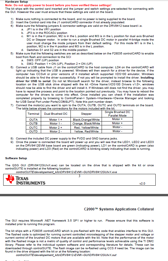
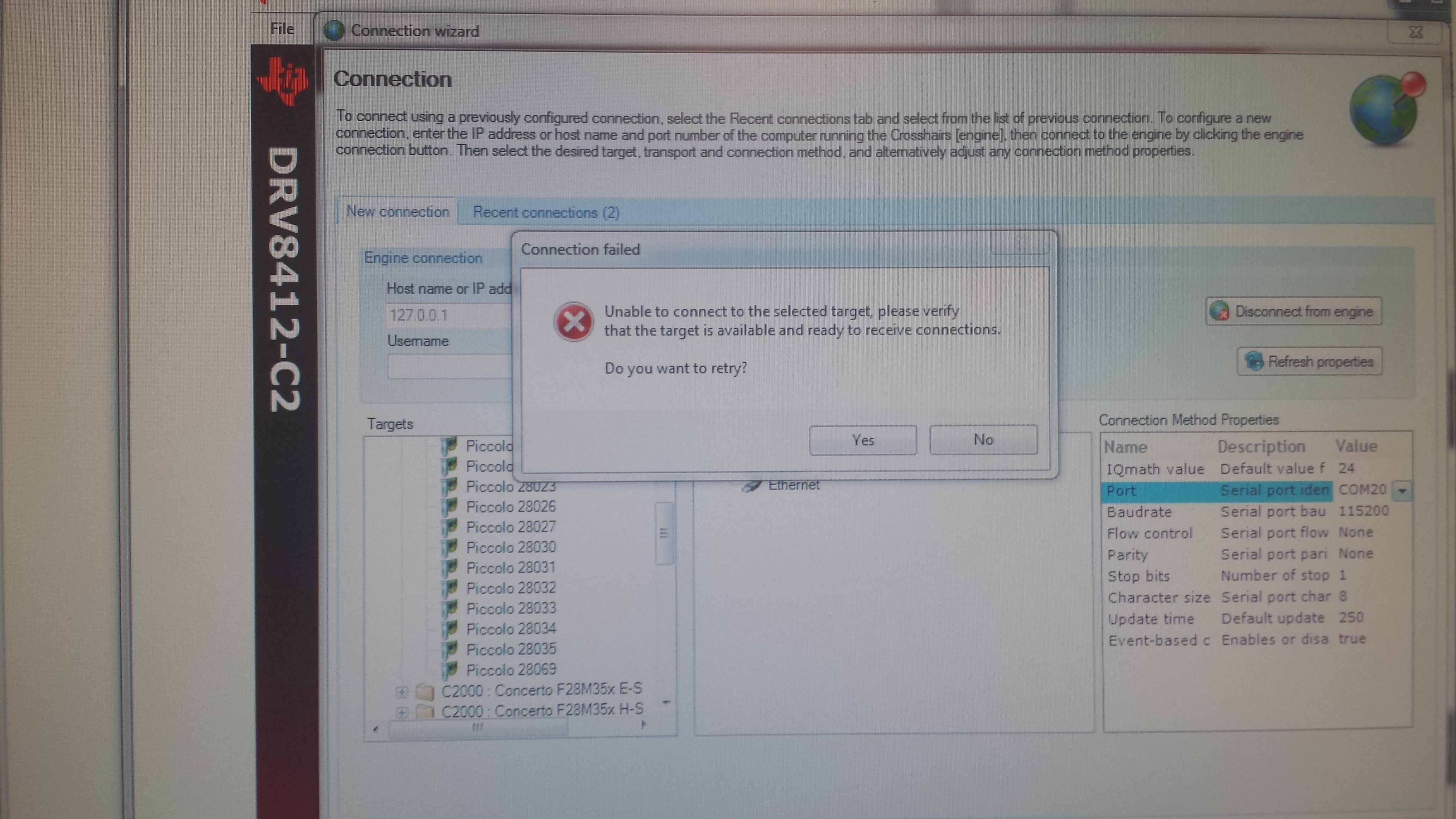
    A follow up test today in the lab when I try to run the GUI provided by the DRV8412( I attached Hardware setup) Step 9 "LD3 does not turn red or blink at all"  and when I try to set the GUI configuration I get an error "Unable to connect to the selected target, please verify that the target is available and ready to receive connections."(attached picture 2). I have tried powering off the motor and using a different C28035. I have the same issue now when I try to run the GUI, it won't make a connection.

  • I'm unaware of this kit and its setup. Wait for an expert opinion on the same.