This thread has been locked.

If you have a related question, please click the "Ask a related question" button in the top right corner. The newly created question will be automatically linked to this question.

GPIO interrupt not always invoke interrupt routine

Other Parts Discussed in Thread: CONTROLSUITE

Hello

I'm working on a F28377D.

I have an external component which generate an interrupt signal on falling edge.

Then I route this hardware signal to the GPIO69 -> Input X-Bar (Input4) -> XINT1 -> INT1.4.

So I used the interrupt exemple to implement my code provided Bellow.

On ISR routine, I make specific operation on External component (via SPI) to clear the interrupt on it then External Interrupt pin goes Up)

This work correctly, but sometime, external Interrupt goes low, but internal ISR routine not called.

When this occurs, I read some registers:

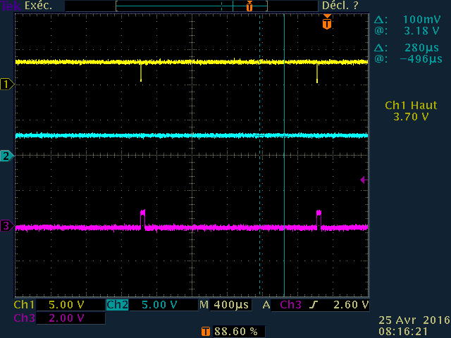
- GPCDAT.GPIO69 is 0 (I read also this state on oscilloscope!

- InputXbarRegs.INPUT4SELECT is well set to 69

- XintRegs.XINT1CR Polarity is 00, Enable is 1

- PieCtrlRegs.PIECTRL.ENPIE is set.

- PieCtrlRegs.PIEIER1.INT4 is set.

- BUT PieCtrlRegs.PIEIFR1.INT4 is clear.

  and PIEACK is 0x0000

So I don't understand why sometime GPIO69 goes low but Int4 flag is not set.

What wan I read to see where interrupt propagation was stopped? (between GPIO69 falling edge and INT4 Flag not set..)?

 Note: When I blocked in this state, I set INT4 Flag with debbuger, then routine is called, so SPI read is done on external  Controller which make GPIO 69 set to 1. Then, next interrupt signal (GPIO69 falling edge) will work again, until few seconds (10 - 20s) where a Falling edge will not trig interrupt routine for unknown reason... 

Thank

Annex: My code:

PieVectTable.XINT2_INT = &Sync0Isr;

PieCtrlRegs.PIEIER1.bit.INTx4 = 1; // Enable PIE Group 1 INT4 (for XINT1)

IER |= M_INT1; // Enable group 1 interrupts


EALLOW;
// GPIO69 is inputs for PDI IRQ
GpioCtrlRegs.GPCMUX1.bit.GPIO69 = 0; // GPIO
GpioCtrlRegs.GPCDIR.bit.GPIO69 = 0; // input
GpioCtrlRegs.GPCQSEL1.bit.GPIO69 = 0; // XINT1 Synch to SYSCLKOUT only 
EDIS;

// GPIO69 is XINT1
GPIO_SetupXINT1Gpio(69);


// Configure XINT1 & XINT2
XintRegs.XINT1CR.bit.POLARITY = 0; // Falling edge interrupt
XintRegs.XINT2CR.bit.POLARITY = 0; // Falling edge interrupt

XintRegs.XINT1CR.bit.ENABLE = 1; // Enable XINT1


__interrupt void EscIsr( void )
 

PDI_Isr();
 

/* reset the interrupt flag */
 PieCtrlRegs.PIEACK.all = PIEACK_GROUP1;
}


  • Hi,

    Did you try increasing the QUALPRD for the XINT pin?

    Regards,
    Gautam
  • I think this will not effect because I configured the Input qualification to SYNC Only. In this case, the QUALPRD has no effect?
    Even if I used Sampling Windows, my interrupt signal goes low and stay at low level because of no interrupt routine is called (in which I made the manipulation to acknowledge the external controller interrupt pin and the pin goes high)
    ...
    I will to increase it... And I also try the async mode and then the sampling windows mode with a QUALPRD value...
  • One more thing, did you follow the steps as in example code that can be found here:
    C:\ti\controlSUITE\device_support\F2837xD\v190\F2837xD_examples_Cpu1\external_interrupt\cpu01

    Regards,
    Gautam
  • Hello

    Like said in my first post:
    "So I used the interrupt exemple to implement my code provided Bellow."
    Then I used exemple in v150 version, not v190 (because of I start from exemple IDDK_PM_Servo_F2837xc which use the v150)
    So my project link library from v150, not v190..

    1) Did you think use v150 library instead of v190 can cause my problem?

    2) I compare provided exemple in v150 vs v190, code exemple is exactly the same

    So i extract only the initialisation part like reported in my first post to activate the external interrupt..

  • Hi,
    Is the above code your *entire* code? Do you have other interrupts and related ISRs in other parts of your code?
  • Hi,

    Instead of SYNC could you try ASYNC path (GpioCtrlRegs.GPCQSEL1.bit.GPIO69 = 3) and see if that makes any difference in behavior.

    Regards,

    Vivek Singh

  • I did it, the result is the same :-(
  • I disabled all other interrupts like that:
    //debug AG PieCtrlRegs.PIEIER3.bit.INTx11 = 1; // Enable PWM11INT in PIE group 3
    //debug AG PieCtrlRegs.PIEIER1.bit.INTx3 = 1; // Enable ADCC1INT in PIE group 1
    PieCtrlRegs.PIEIER1.bit.INTx4 = 1; // Enable PIE Group 1 INT4 (for XINT1)
    //debug AG PieCtrlRegs.PIEIER1.bit.INTx5 = 1; // Enable PIE Group 1 INT5 (for XINT2)
  • Hi,

    It'll be helpful if you can attach full project (if not issue) and also the snapshot of scope with GPIO waveform.

    Regards,
    Vivek Singh
  • Hello

    Please find the project, and two snapshot.

    In yellow (CH1) , it is the GPIO69 pin signal which trig the interrupt.

    CH2 is the second interrupt, but disable in my tests.

    CH3 is the DACB output of the evalboard IDDK Rev2:

    I Set Dac out to #1000 on Begin of the interrupt source code (&ESCIsr), and set to 0 at the end of it. (We can see when this run correctly, the GPIO69 signal is acknowledge thank to work done in the ISR.

    On the ground task (450µs C0 task), I pull  the GPIO69 state, if it is to 0, I set DACb to 4095...

    Pjt.rar

  • Same with a large base time to see on interrupt Ok and the next where ISR routine never called.

  • Hello

    I think I found the use case which reproduce always the problem.
    In fact this is linked to my previous post here:
    e2e.ti.com/.../501993

    My goal is to call a routine when external pin falling low. Sometime, I need to disable the associated interrupt.
    Then I use the exemple which configure the XINT1 to the PIEIER1.INTx4

    The macro to enable/disable this interrupt was:

    #define DISABLE_ESC_INT() (PieCtrlRegs.PIEIER1.bit.INTx4 = 0)
    #define ENABLE_ESC_INT() (PieCtrlRegs.PIEIER1.bit.INTx4 = 1)

    But with this, a specific case make IT PIEIE1.Intx1 occurs (refer to the post linked above)

    So I change the macro to this:
    #define DISABLE_ESC_INT() (XintRegs.XINT1CR.bit.ENABLE = 0);
    #define ENABLE_ESC_INT() (XintRegs.XINT1CR.bit.ENABLE = 1);


    But with this, if the pin goes low between DISABLE_ESC_INT and ENABLE_ESC_INT, when ENABLE_ESC_INT is called and the external pin is LOW, the interrupt not occurs. But in my case I need it!

    So the question is simple:
    - How disable the calling of ISR routine for a protected code area and call it if when the interrupt is enable again the pin is low?

    (In other word, I need a detection on Low state, not on Falling edge only, but I read the datasheet, it seems no possible?)

    Thank for your help.


    For information, this protected area is to avoid interrupting a SPI communication which is used during the ISR routine code...
  • Hi,

    But with this, if the pin goes low between DISABLE_ESC_INT and ENABLE_ESC_INT, when ENABLE_ESC_INT is called and the external pin is LOW, the interrupt not occurs. But in my case I need it!

    This is correct. Generally interrupt is used for CPU since CPU is busy in some other operation. I this case if CPU is going to disable/enable interrupt then before enabling, you can check the status of external interrupt pin (via GPIODAT register) and if it's already low then force the interrupt by SW (setting the bit in IFR register)on same interrupt vector to execute ISR.

    Will that work ?

    Regards,

    Vivek Singh

  • Ok

    I will try

    Thank you