


Other Parts Discussed in Thread: MOTORWARE
I'm developing a VFD based on my own inverter stack and control PCB using F28069 and InstaSPIN.
My motor is kinda special so that it's hard to finish the motor identification procedure. (It's blower so that it has initial load)
So I just conducted R/L and Rs estimation and then put those values in code of lab5a.
The motor could run, and was controlled well by Iq reference from 5A to 20A.
But the problem was the motor speed didn't vary. It just changed slightly even though its rated current at 18krpm is around 25A.
I found that frequency of the motor current waveform captured by oscilloscope didn't correspond to krpm value on CCS window.
I also found that Id fluctuated not keeping zero.
So I drew the motor phase voltage which was got by the following code on CCS.
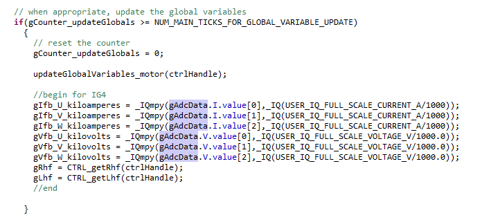
I believed that gAdcData.V.value is the value that already applies the bias. So I expected to see AC motor voltage waveform.
But it wasn't actually. Please see below captured image.
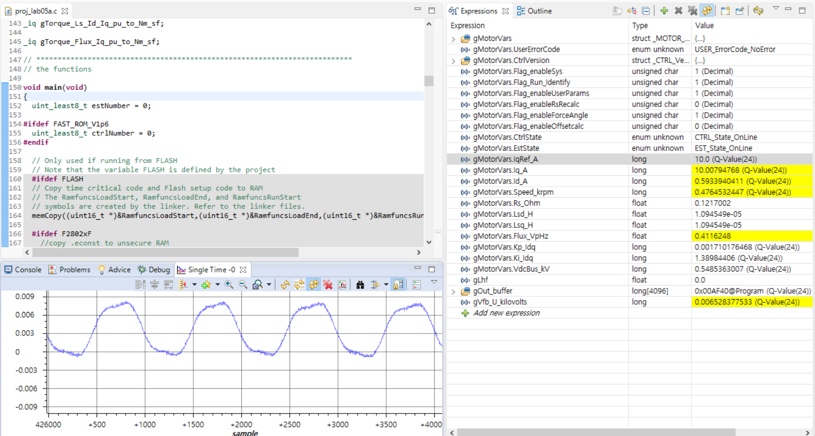
The motor U-phase voltage seemed wrong. (It has offset or bias) I guessed that's why the motor speed estimation was also wrong and the motor speed didn't change even though I increased the motor Iq reference and the motor current tracked it.
Is there anyone who suffered from the similar problem or can help me? I have to solve this problem and make a progress urgently cuz the deadline is coming soon. OMG

