This thread has been locked.
If you have a related question, please click the "Ask a related question" button in the top right corner. The newly created question will be automatically linked to this question.
We have discovered on multiple (all) units that we can permanently lock up the microcontroller to where it even ignores the XRS pin being pulled low with valid supply voltages.
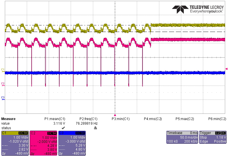
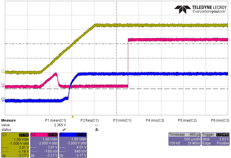
If we power multiple microcontrollers using a power source that is inadequate for the number of controllers connected, The VDDIO rail will start to effectively oscillate between approximately 2.8 and 3.2V. Whether or not an actual reset occurs on the XRS pin depends on if and when the other microcontroller resets as well, thereby reducing the load on the common bus. Either way the rail voltage is oscillating. When an additional power source comes on line, the rail voltage will stabilize to 3.3Vdc, but the processor is now locked up. Even grounding the XRS pin does nothing unless the power is completely removed and reapplied to the part.
We also forced BORENZ to 0, but no change.
See attached waveform showing oscillation until more power is available. Top trace is VDDIO, middle trace is XRS, bottom trace is VDD. We never saw anything happen to VDD.
Hi Adam,
1. When AC is first applied, the power on waveform looks like this:
Yellow waveform is VDDIO, Red is XRS, and Blue is VDD (Core). The VDD is internally derived from the regulator in the microcontroller. The microcontroller comes up and operates normally and all is well.
Some arbitrary amount of time later (it doesn't matter how long) AC is removed, and a secondary supply source is used to power the microcontroller. However, this supply is current limited, and as a result, the VDDIO voltage starts to oscillate. The transition to this second mode is shown below:
This mode of operation will continue for another arbitrary amount of time (doesn't matter how long). During this mode, the micro does not communicate.
Finally, the AC to the system is restored, and the transition back to normal VDDIO looks like this:
Afterwards, the processor does not communicate, and it cannot be reset by grounding XRS. Also, grounding the TRST pin does nothing. The only way to reset and correct this issue is to completely power down the unit, and restart per the first waveform.
2. Yes. See above
3. The devices are booting from flash. Yes the pins are set correctly.
4. We’ve tried both ways. Leaving the default. Also tried to force it with “SysPwrCtrlRegs.BORCFG.all= 0;”
a) The result is the same.
b) Note: This is was done in both the boot loader and functional code.
Regards,
Jeff
It is, but I don't think it is meaningful. Our scope has a limited degree of common mode rejection, plus there is pickup in even the small probe loop that remains after we install a probe point that doesn't use the pigtail on the scope. We also have common mode cores on the scope leads. Anyway, here is the result of triggering on the noise spike:
Note: each VDDIO pin is decoupled by a ferrite bead and a 2.2uF ceramic capacitor. There is a solid ground plane throughout the design (layer three of 4 layer board). The capacitor is on the back side under the processor with short connection to VDDIO and GND. If there were really 2V in 1 nSec across the capacitor it would require a current on 4.4KA to produce this fast of a change.
To confirm that some of the noise is still present with the VDDIO scope probe looking at its own ground connection rather than VDDIO, this second waveform is taken with channel one measuring the scope probe ground:
Although the noise is somewhat lower, its still there on the probe ground.
But if an EMI transient can upset the processor, would you expect that this would also cause the processor to ignore the XRS and TRST pins? Would the oscillator have to stop running for that to be the case?
FYI, this product has been through EMI, EMC, and surge testing at 4KV without upsetting the processor. It is ready for release except for this one issue.
Regards,
Jeff
VDDIO is powered from a LM1117 type LDO. The alternate sources of power are two stages up, at the input of a 5V switching regulator. When the input of the 5V switching regulator drops too low its output starts to drop which in turn causes the 3.3V LDO to drop.
We tried to force the 3.3V oscillation to have a lower voltage at the bottom of oscillation as shown below:
Channel 1: 12V input to 5V reg. Channel 2: XRS, Channel 3: VDDIO.
Under this condition, the microcontroller recovers normally.
It seems to me that the issue could be related to the fact that the recommended minimum operating VDDIO range is 2.97V, while the BOR shutdown threshold can be anywhere from 2.42V to 3.135V according to the data sheet. Under some conditions the VDDIO recovers from a level near BOR without actually generating a XRS reset signal.
Unfortunately, I cannot control when the 12V into the 5V regulator which feeds the 3.3V regulator will recover to full voltage, so I cannot control how far the VDDIO voltage will sag before recovering.
Can TI guarantee that the BOR circuit will generate an XRS signal before the VDDIO voltage is too low for the microcontroller operate correctly?
Regards,
Jeff