This thread has been locked.

If you have a related question, please click the "Ask a related question" button in the top right corner. The newly created question will be automatically linked to this question.

How to do current control in lab11a with speed as reference?

Hi all,

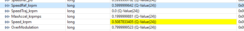
I want to clarify that n lab11a i have to provide speed reference, So does that mean it is speed control based lab? or both speed control plus current control.

If both controls are there then does that mean both are simultaneously working in this lab? How can i make this lab as current control with speed as reference?

Thanks

  • in Lab5b, according to flow chart both speed control and current control are there. So is this lab is better than lab5a?
  • Lab11a can work with both speed and current close loop. Please refer to lab user guide to understand the difference between lab05a and lab11a. Lab11a is a project with the least FAST functions calls, and without contoller module.
  • Yes Yanming, i know that lab11a can work on both the controls. and also i have implemented that one by one.
    I want to ask that are these both the controls working simultaneously in this lab or not? and if both can work then how can i implement both of them so as to get current control as main parameter with reference of speed.
  • InstaSPIN-FOC control scheme works on a cascade of speed and current control loops, with the speed reference working to command a current reference. Whenever you're commanding a speed reference, you're inherently commanding a current reference as well. If you were to only use one of the control loops, it would have to be the current loop only.
  • Hi Sean, 

    Lab11a, how can I directly control the current loop by disabling the speed controller and setting the Iq reference to current controller ?Could you please point me the functions/variables in the lab11a code implementation ?

    I’m trying to combine the lab04 (torque mode control) and lab11a ,  so I can switch between two control mode separately at a time.  I’ve created the two control mode: 1) speed control, 2) torque control ( current control ) based on the lab11a. The speed control seems work fine based on the example code.

    When I try to reuse two functions in the lab04, CTRL_setFlag_enableSpeedCtrl()  is to disable the speed control , updateIqRef() is to setup the Iq reference for the current controller. I got lots of error that was complain some broken link or symbolic and also can’t be traceable back because those functions were in ROM.

    Thanks,

    Yz

  • lab11a isn't using the CTRL, so the CTRL functions from earlier labs don't work.

    in lab11a to set a torque reference you will just be setting the Iq refValue (in pu) yourself, instead of the values created by the speed controller

          // get the Iq reference value
          refValue = gIdq_ref_pu.value[1];

    recall though that even in torque mode you need to set a speedRef into the EST with the same sign as the IqRef. If you are only going to command +Iq, just having a +SpeedRef all the time is fine.

  • Hi Chris, 

    Thanks a lot for all the suggestion. 

    1)Does that mean I don't have to disable the speed control loop by  CTRL_setFlag_enableSpeedCtrl(ctrlHandle, false) like earlier lab04? If I don't use it, when I run it in the torque control mode, does it affect any estimation value from FAST observer such as angle, flux, torque, speed ? Any flag I should set when I switch from speed to torque mode for the FAST observer ? Still try to understand how to use the FAST observer 

    2) If I directly assign Iq from watchwindow like  refValue = _IQmpy(gMotorVars.IqRef_A,_IQ(1.0/USER_IQ_FULL_SCALE_CURRENT_A)), then we should be able to command any Iq value in real-time ? anything else I should be aware of for changing the Iq command in the watch window?

    Thanks,

    Yz

  • 1. No, you aren't using the controller, so it doesn't matter.
    2. in lab11a gMotorVars.IqRef_A doesn't exist. If you want to set this up as a variable yourself you can.
    you will need to make modifications to the code in 11a to run in torque control mode.
  • For your comments "set a speedRef into the EST with the same sign as the IqRef", in order to get the estimation from observer, when I modify to implement the torque mode and call the function void EST_run() in lab11a, does that mean I still need to provide the speed reference here ?
  • yes, you still need to provide any speed reference with matching polarity/sign so that the direction is correct inside FAST.
  • Hi Chris, 

    Now I'm running the speed control by using lab 11a, however I found that the speed is limited around 5000rpm no matter what speed reference I set.

    1) Any idea why? How can I  full speed range control ? The motor I'm running have rated speed 1050rpm, rated torque 2.27N.m 

    2) I tried to increase the modulation index from 0.5 to 0.7 to see if it can increase the speed range, but it seems not working. Is this speed limitation related to  over-modulation ?

    And thanks a lot for previous help, I've completed the torque mode control. 

    Thanks,

    Yz

  • Overmodulation should not be set higher than (2/3)

    I would suppose you don't have enough Vbus for this motor to reach the rated speed

    or perhaps the you have the #of poles incorrect, so it's reaching the top speed but the KRPM is incorrectly calculated

  • how do we evaluate Vbus is enough to drive the motor ? Now I'm measuring it and got 321V on the scope, on the debugger window it shows 325V.

    also how do we know if the #of poles is incorrect? anything we can verify it?
  • what voltage is used for the speed rating of the motor?

    you can run the motor at 60 RPM and see if it is spinning at 1 rev per second or 120 RPM and 2 revs per second)
  • I set motor running at 60rpm, on the scope I measured the 3-phase current on the motor, it's around 1KHZ.
    since 1 revolution/second = 1HZ , does that mean the #of poles is wrong ?
  • Sorry, it's 4HZ measured on the 3phase current. Does that tell us anything?
  • if we use rpm = 120*Freq/#of poles, it seems right here 120*4HZ/8 = 60RPM. That's exactly the speed feedback from FAST observer.
    Still not sure why the speed is limited to half ?

    Here is manufacturer data: 1/3HP 600-1200RPM 208-230Voltage 60HZ
  • what USER_MOTOR values are you using? Your flux value may be too high.
    Enable PowerWarp and you will reach the speed. Your flux value will drop. If you slowly add the rated load the flux should increase to produce the torque while still maintaining the speed. This is the flux you should use for USER_MOTOR value
  • 1) How do we calculate MOTOR_RATED_FLUX ?

    The motor parameters I got is 96Vpeak/1000rpm, then I use the equation from instaSPIN manual 96*60/1000/#of pole pairs /sqrt(3) = 0.831 . When I run the torque control mode, this parameter works very well; in speed control mode, this parameter works well under any 500rpm. 

    2) But I do see the problem with this rated flux parameter, when I decrease the rated flux and run it in the speed control. I can see the speed can goes up 500rpm, but again is being limited at some level. So that's back to my first question how to calculate this parameter?

    3) Does the PowerWarp only applied to the ACIM ? I'm running an PMSM motor.

    Here's the user parameter I'm using:

    #define USER_MOTOR_TYPE                 MOTOR_Type_Pm

    #define USER_MOTOR_NUM_POLE_PAIRS       (4)        

    #define USER_MOTOR_Rr                   (NULL)      

    #define USER_MOTOR_Rs                   (5.49506474)  

    #define USER_MOTOR_Ls_d                 (0.071925148)

    #define USER_MOTOR_Ls_q                 (0.071925148)  

    #define USER_MOTOR_RATED_FLUX           (0.831)        

    #define USER_MOTOR_MAGNETIZING_CURRENT  (NULL)      

    #define USER_MOTOR_RES_EST_CURRENT      (0.31)        

    #define USER_MOTOR_IND_EST_CURRENT      (-0.31)      

    #define USER_MOTOR_MAX_CURRENT          (2.4)          

    #define USER_MOTOR_FLUX_EST_FREQ_Hz     (20.0)

  • 3. PowerWarp is just for Induction motors. The way you stated your motor rating made me think it was induction. Very strange to see a rating of 210-230V 60 Hz for a synchronous machine.

    I would increase USER_MOTOR_MAX_CURRENT

    I would guess you are saturating the Iq PI output. 

  • How do we determine the USER_MOTOR_MAX_CURRENT? Is it coming from the motor spec ? like maximum motor current? 

    Or from control board hardware spec ? if it's control board, I'm using the HV kit from TI, where can i check to get the maximum current ?

  • it is the peak phase current required to meet the torque spec. it should not exceed the peak current rating of the board.
    for the TI HVKIT you can use (9.9) maximum
  • Hi Chris,

    1) How we set the USER_VOLTAGE_FILTER_POLE_Hz ?

    In default, the source code set this value to 800 like following:

    #define USER_IQ_FULL_SCALE_FREQ_Hz        (800.0)   // 800 Example with buffer for 8-pole 6 KRPM motor to be run to 10 KRPM with field weakening; Hz =(RPM * Poles) / 120

    The motor I'm using now is rated speed 1050rpm, 8 poles, rated torque 2.27N.m , should I change this parameter value to 80 since it should greater than 1050rpm*8/120 = 70

    2) I found this post https://e2e.ti.com/support/microcontrollers/c2000/f/902/t/319433#pi316717=2  is it still working today ? 

    The issue I have now is whenever I try to integrate the graph.c, graph.h in lab05h to lab11a , it's either trip the control board or maybe burn the motor. It looks like related to the buffer, memory issue etc. , but I'm not so clear why. 

    Please advise. 

  • 1) this is set by the hardware filter on the voltage sense circuits. it is typically in the 300 Hz range. If you are using a TI EVM don't change the value from the default.

    If your motor is only 80 Hz max you could change USER_IQ_FULL_SCALE_FREQ_Hz to (200.0) as the lower limit.

    2) in general - with the TI EVM - using the default user.h values will work for most motors. It's not recommended to change them unless absolutely necessary.
  • Thanks a lot. 

    You mentioned it's typically in the 300Hz range. I'm wondering how we get this range? I took a snapshot of the voltage sensor circuit, any calculation we could do from the schematic to get this range. 

    My concern is as I developing the software, I'll eventually have to use our own control board, then how can get reasonable parameters setting based on the hardware and motor parameters. That's why I'm trying to understand how we setup the parameters in user.h. 

  • You can find the equation for the calculation of USER_VOLTAGE_FILTER_POLE_Hz in Section 5.2.4 of InstaSPIN user guide (SPRUHJ1G), USER_VOLTAGE_FILTER_POLE_Hz =1/(2*PI()*R*C).
  • Thanks a lot.  but I still confused about how this number is being calculated ?

    does this guide substitute the wrong number ? please help list correct one ?

  • The equation is correct, but the calculation result is wrong. For figure 5-8, it is as below
    f(filter pole)=1/(2*PI()*47*10^-9*(42.2*4.99)/(42.2+4.99)*1000)=758.856Hz