it is bit of confusing what does 'DNP (do not populate)' really mean in the schematics of the control card.
Does this actually mean that these components have been populated already somewhere? So we do not need to populate them?
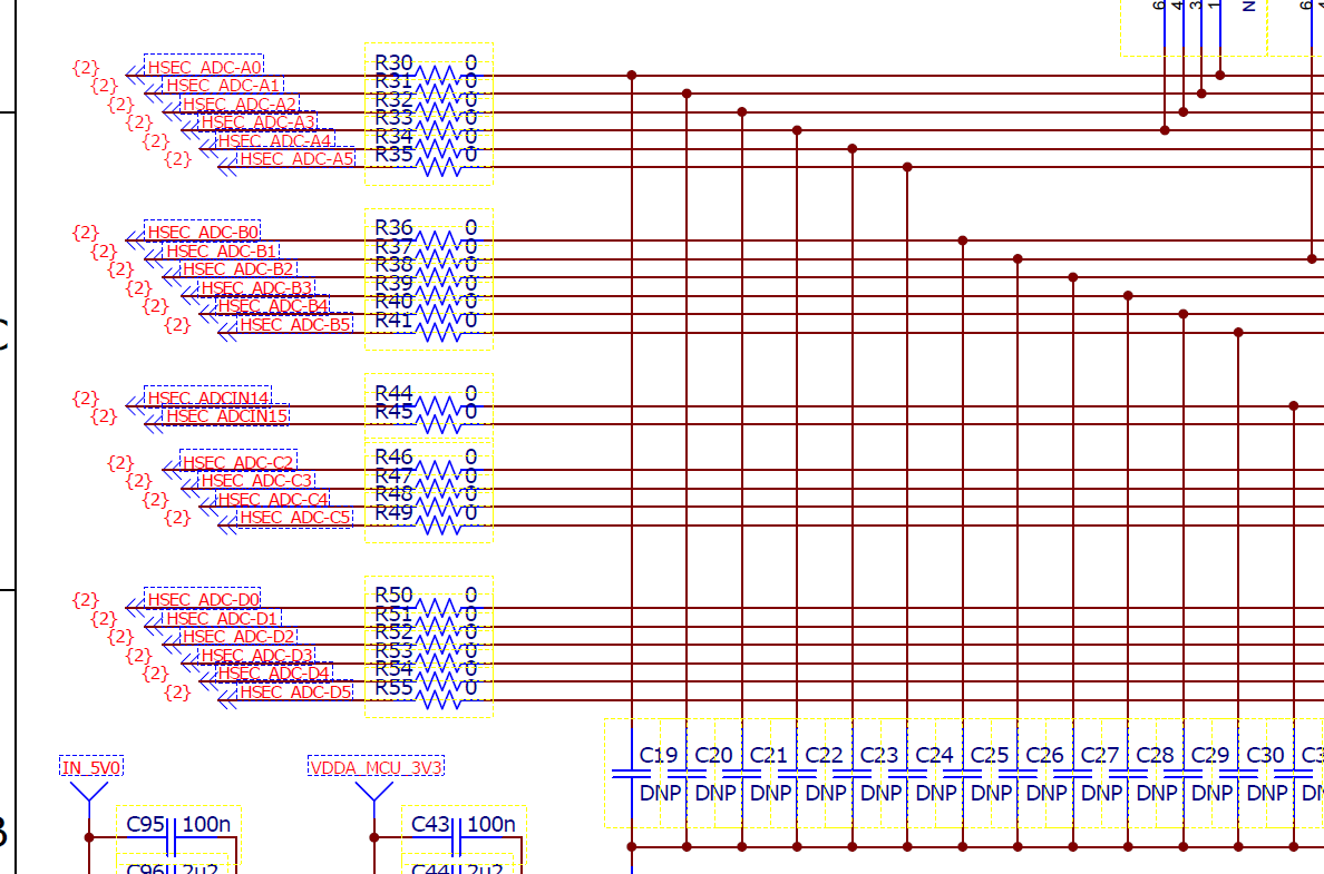
I am using 28377d experimenter kit. The problem is with the ADC conversion. Currently I am getting really distorted results with great noise. I think one of the reasons could because of the RC filters connected with the ADC inputs. From the schematics, it shows these filters including resistors and capacitors (R30-R55, C19-C42 etc.). However, they are labelled with DNP. It is actually confusing.
This also affects the ADC references via R42 and R43.
1) Do I actually need to populate these components labelled with 'DNP'? Do they actually exist in the control card or chip?
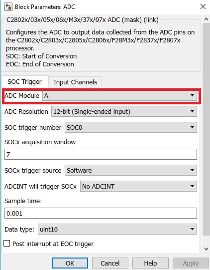
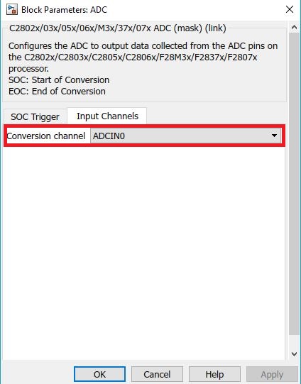
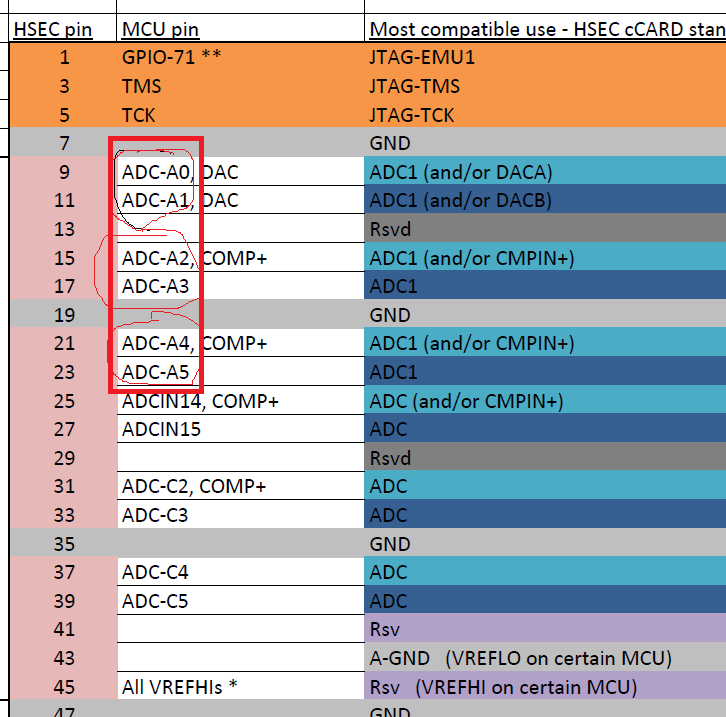
2) By the way, is this true: ADCIN0=ADC_A0 (ADCINA0), ADCIN1=ADC_ADC_A1 (ADCINA1), ADCIN2=ADC_A2 (ADCINA2) and so on? I am using MATLAB/Simulink to programme, ADCIN0,1,2,3 appear in the Simulink ADC block. I wonder if there are true.
Thanks everyone