


Part Number: TMS320F28020
Tool/software: Code Composer Studio
Issue description:
Message information
55 AA 00 00 00 00 00 02 FB 95 00 01 CD 1C 42 5B 00 6E 31 9D 05 04 00 00 00 C8 00 66 66 66 FF 37
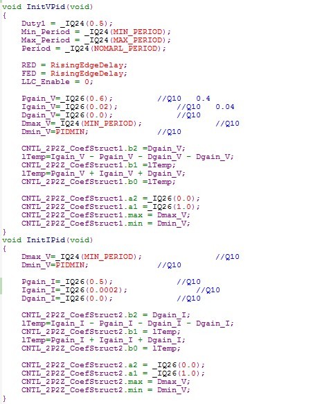
1.I used TMS320F28020, The frequency is 50M, I call the CNTL_2P2Z.Asm function.
2. After I power on the PCB, I found 2P2Z operation result error, is a great value, is not between set the Max and Min.
3.Doing experiment 1.Set the progRAM length 400, from the map view the actual length of (160), set the dataRAM length B00,
from the map view the actual length of for (65). Then the 2P2Z_1 calculation results in the setting of range (000000C0-00666666)
,but 2P2Z_2 value is not within the scope of, and as a fixed value (4158465A) is beyond the scope .
4.Doing experiment 2.Set the progRAM length 800, from the map view the actual length of (160), set the dataRAM length 800,
from the map view the actual length of for (65). Then the 2P2Z_2 calculation results in the setting of range (000000C0-00666666)
,but 2P2Z_1 value is not within the scope of, and as a fixed value (319D0504) is beyond the scope .
5. The proggram is only modify the length of the progRAM and dataRAM CMD file, and other places do not make any changes.
6. A message reading: (55 AA) begin message -- -- -- (00 00 00 00) - reference value
(00 02 FB 95) 2P2Z - 2 of 2 input, (00 01 CD 1C) 2P2Z - 1 input
(42 5B 00 6E) flag, no practical significance
(31 9D 05 04) 2P2Z - 2 output, (00 01 CD 1C) 2P2Z - 1 output

7. Can you tell me how to make 2P2Z-1 and 2P2Z-2 the output of the normal at the same time? Where is my problem ?
10. How to properly allocate the size of the progRAM and dataRAM, whether to have this document or notice?

