Part Number: LAUNCHXL-F28377S
Hi All,
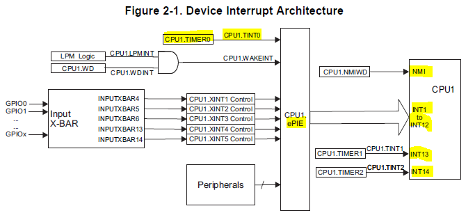
I read code example of "cpu_timers_cpu01", what is a purpose of __interrupt void cpu_timer0_isr(void) function?
Best Regards,
Takano
Part Number: LAUNCHXL-F28377S
Hi All,
I read code example of "cpu_timers_cpu01", what is a purpose of __interrupt void cpu_timer0_isr(void) function?
Best Regards,
Takano