This thread has been locked.
If you have a related question, please click the "Ask a related question" button in the top right corner. The newly created question will be automatically linked to this question.
Hi Champs,
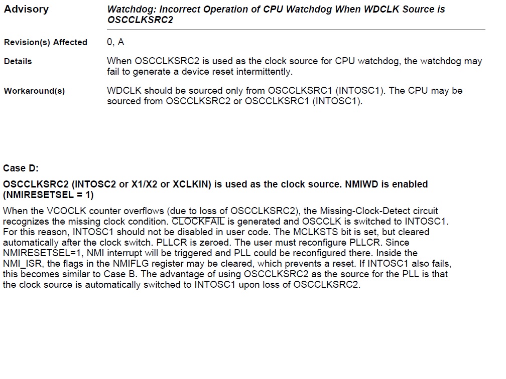
My customer is designing digital power product using F28035. Now they found MCU would reset by external interference. They found PLL would be corrupted by interference, looks CLOCKFAIL occured.
XTAL clock is 20MHz, and CPU clock is set to 60MHz, while XCLKOUT is used to monitor the SYSCLKOUT.
The clock initialization code is as follows.
void InitSysCtrl(void)
{
DisableDog();
EALLOW;
SysCtrlRegs.PCLKCR0.bit.ADCENCLK = 1; // Enable ADC peripheral clock
(*Device_cal)();
SysCtrlRegs.PCLKCR0.bit.ADCENCLK = 0; // Return ADC clock to original state
EDIS;
XtalOscSel();
InitPll(6,2);//(OSCCLK * 6)/2=20M*6/2=60M
InitPeripheralClocks();
}
void XtalOscSel (void) {
EALLOW;
SysCtrlRegs.CLKCTL.bit.XTALOSCOFF = 0; // Turn on XTALOSC
SysCtrlRegs.CLKCTL.bit.XCLKINOFF = 1; // Turn off XCLKIN
SysCtrlRegs.CLKCTL.bit.OSCCLKSRC2SEL = 0; // Switch to external clock
SysCtrlRegs.CLKCTL.bit.OSCCLKSRCSEL = 1; // Switch from INTOSC1 to INTOSC2/ext clk
SysCtrlRegs.CLKCTL.bit.WDCLKSRCSEL = 1; // Switch Watchdog Clk Src to external clock
SysCtrlRegs.CLKCTL.bit.INTOSC2OFF = 1; // Turn off INTOSC2
SysCtrlRegs.CLKCTL.bit.INTOSC1OFF = 1; // Turn off INTOSC1
EDIS;
}
void InitPll(Uint16 val, Uint16 divsel)
{
volatile Uint16 iVol;
// Make sure the PLL is not running in limp mode
if (SysCtrlRegs.PLLSTS.bit.MCLKSTS != 0)
{
EALLOW;
// OSCCLKSRC1 failure detected. PLL running in limp mode.
// Re-enable missing clock logic.
SysCtrlRegs.PLLSTS.bit.MCLKCLR = 1;
EDIS;
// Replace this line with a call to an appropriate
// SystemShutdown(); function.
__asm(" ESTOP0"); // Uncomment for debugging purposes 卡死在这个位置了!!!!!
}
......
}
The watchdog code:
SysCtrlRegs.WDCR = 0x002A;
WDCLK = OSCCLK/512/2 = 20M/512/2=19.531kHz=51.2us;
Watchdog overflow time = 51.2us*256=13.1ms
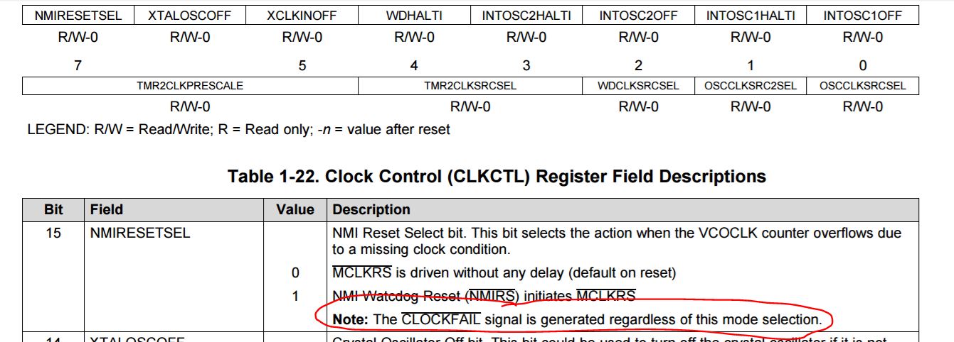
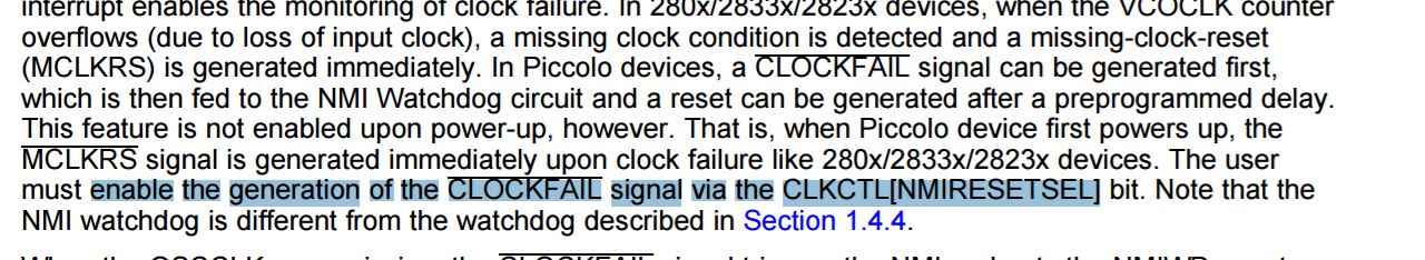
If CLOCKFAIL occured, NMIWD will reset the device. In there code, they set NMICFG[CLOCKFAIL] and NMIWDPRD, NMIRESETSEL = 1. You can find the scope captures as follows. BLUE waveform is PWM output, YELLOW wavefrom is XCLKOUT.
1. NMIRESETSEL = 1,NMIWDPRD=3000. when CLOCKFAIL occurred, PWM frequency was changed from 100KHz to 33KHz, and XCLKOUT from 60MHz to 20MHz, and the time is about 150us.
After reset, SYSCLKOUT is 60Mhz lasting 50us.
After that, NMIRESETSEL = 1,NMIWDPRD=6000,
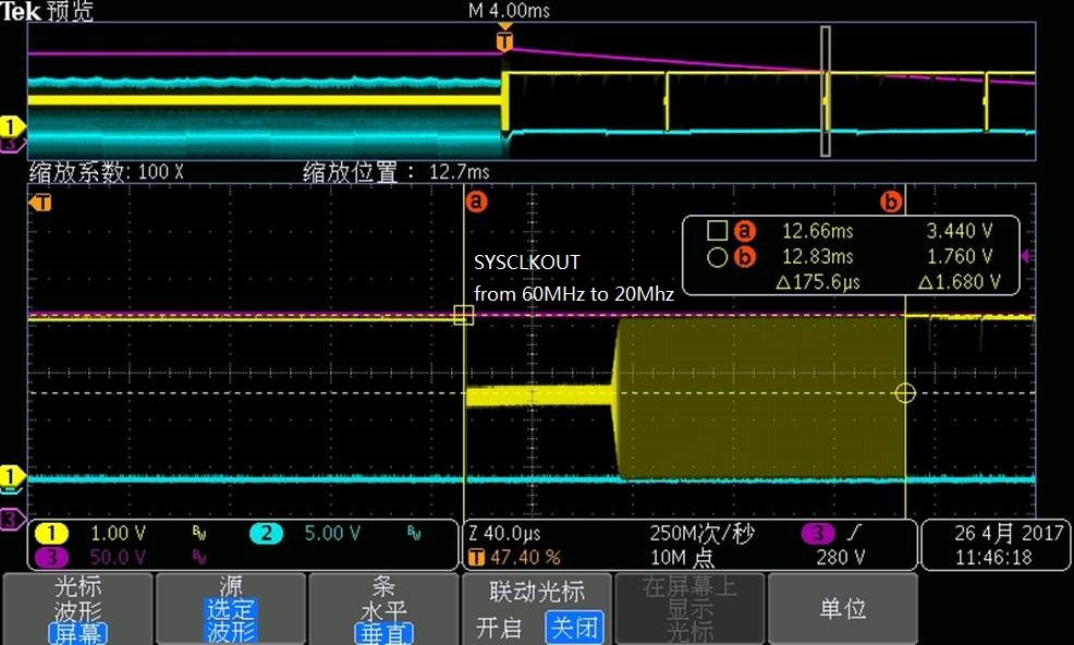
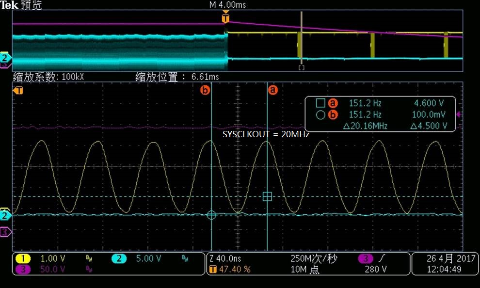
Would you kindly help to analyze why this failure happened? After reset, why SYSCLKOUT changes from 60Mhz to 20MHz? Thanks.
BR,
Young.
Young,
It is important to distinguish a true clock failure from other type of disturbances. (Please refer to SPRUH18G on the web; I understand it is for F2806x devices. However, the missing-clock-detect feature works the same on F2803x. This TRM, which was released only a few days back on the web has lot of clarifications on how a missing clock situation is handled. Customer's situation is case D in the TRM. See attached graphic).
Hareesh,
In my customer's code, INTOSC1 is turned off, and also there is no NMI ISR for NMI WD interrupt, and NMIFLG is not cleared. Can you kindly suggest what would happen when external clock missed?
I am asking customer to provide more information as you mentioned, and will send the feedback to you soon.
Thanks a lot.
BR,
Young
If there is no NMI ISR to handle the situation, the NMIWD counter would overflow and the device would get reset, which is what you are seeing.
Hareesh,
Please find my customer's reply as follows.
Hareesh J said:
- Exactly what disturbance is this? Is it created deliberately as part of testing or is this (random) disturbance inherent in the system.
It could be common mode disturbance or differential mode disturbance inherent in their DCDC system. Can you suggest how the EMI disturb to normal working of XTAL? If there is any interference on XTAL, does PLL would be corrupted? Which pins would be sensitive to EMI to disturb XTAL oscillating?
Hareesh J said:
- How did you ascertain that PLL is "getting corrupted"?
(1) if NMIRESETSEL = 0, disable NMIWD, on XCLKOUT a 50us pulse(60MHz) would be found every 6ms, then XCLKOUT pins was high.
(2) If NMIRESETSEL = 1, NMIWDPRD=0xFFFF, XCLKOUT frequency was changed from 60MHz to 20Mhz. Looks PLL is corrupted.
Hareesh J said:
- What happens when you do not disable INTOSC1?
Customer will test, and feedback to you soon.
And also another question is the generation of CLOCKFAIL signal, there is a confusion from TRM. Would you kindly check this?
In SPRUH18G, on P78 "Note: The CLOCKFAIL signal is generated regardless of this mode selection."
From P93, it is said "The user must enable the generation of the CLOCKFAIL signal via the CLKCTL[NMIRESETSEL] bit."
Thanks.
BR,
Young
So this is not a "noise test" customer is deliberately creating, but noise that is inherent in the system. So, this problem could occur at random times.
It is definitely possible that EMI is disturbing the operation of the crystal oscillator. Do you notice that the XTAL oscillator goes into a state where it doesn’t recover at all? i.e. it stops oscillating or do you think the system is merely getting a reset because of the disturbance?
Questions I need answers for:
What happens when INTOSC1 is not turned off?
Is the problem seen if INTOSC1 is used as the clock source?
Any difference when WDCLK is switched to INTOSC1?
If there is no NMI-ISR, why even configure NMIWDPRD register? What is achieved by delaying the reset?
I am checking on the documentation confusion.
Hareesh J said:It is definitely possible that EMI is disturbing the operation of the crystal oscillator. Do you notice that the XTAL oscillator goes into a state where it doesn’t recover at all? i.e. it stops oscillating or do you think the system is merely getting a reset because of the disturbance?
Looks XTAL oscillator is still working.
Hareesh J said:What happens when INTOSC1 is not turned off?
If INTOSC1 is still turned on, the DCDC power module would be burnout when disturbing the XTAL. What I am thinking is customer needs to enable TZ5 to trip the PWM out. So they will test again.
Hareesh J said:Is the problem seen if INTOSC1 is used as the clock source?
If using internal oscillator, i.e. INTOSC1, DCDC power module was also burnout once.
For other questions, I will persuade customer to enable TZ5 to ensure there is no damage occurred, then answer you questions
Thanks.
Young
The line
"The user must enable the generation of the -CLOCKFAIL signal via the CLKCTL[NMIRESETSEL] bit" should read
"The user must enable the generation of the NMI signal via the CLKCTL[NMIRESETSEL] bit "
This will be fixed in future revisions of the documentation.