This thread has been locked.

If you have a related question, please click the "Ask a related question" button in the top right corner. The newly created question will be automatically linked to this question.

DRV8301-69M-KIT: Running 2 SPI slaves in Motorware labs SPI implementation

Part Number: DRV8301-69M-KIT
Other Parts Discussed in Thread: MOTORWARE, C2000WARE, CONTROLSUITE, DRV8301

I am running 2 Picollo SPI slaves (with a Raspberry PI master), using the motorware labs, on one SPI bus (using 2 addresses).

When each of them is connected separately, everything works fine. When both are connected, communication from slave to master is lost (SOMI). From checking by a digital scope, my impression is that both Picollo's try to hold the data line high (1) when they are not active (SOMI data line has active low implementation from Motorware).I see many spikes on the data line, coninciding with the clock pulse.

When discussing with somebody far more knowledgeable, he suggested to switch the data SOMI GPIO's to input when they are not active.

My questions:

1. why is this not done as a default in the Motorware labs?

2. if I want to modify this myself, where to best make this modification to have a clean implementation?

3. Could this be a feature request for a future Motorware update?

BTW, thank you again for this great platform. I love the performance and the efforts made to get starters on board, including properly maintaining this forum from TI staff as well.

Kind regards,

Tomas

  • Next efforts but not yet successful.
    Based on www.ti.com/.../sprug71b.pdf 1.4.2.2 Slave Mode

    in main set the slave out port to high impedance:
    // set the hardware abstraction layer parameters
    HAL_setParams(halHandle,&gUserParams);
    // Disable slave output
    SPI_disableTx(halHandle->spiAHandle);

    in mainISR when reading from/writing to SPI:

    unsigned int register_count = ((unsigned int)(halHandle->spiAHandle->SPIFFRX) & 0x1F00) >> 8; // Mask 9th-13th bit + 8 bit shift

    if (register_count >= 4) {

    // Enable and re-disable slave output
    // to make input high impedance state
    // to allow multiple slaves
    SPI_enableTx(halHandle->spiAHandle);
    halHandle->spiAHandle->SPITXBUF = output1;
    halHandle->spiAHandle->SPITXBUF = output2;
    halHandle->spiAHandle->SPITXBUF = output3;
    halHandle->spiAHandle->SPITXBUF = output4;

    input1 = (unsigned int)(halHandle->spiAHandle->SPIRXBUF);
    input2 = (unsigned int)(halHandle->spiAHandle->SPIRXBUF);
    input3 = (unsigned int)(halHandle->spiAHandle->SPIRXBUF);
    input4 = (unsigned int)(halHandle->spiAHandle->SPIRXBUF);
    SPI_disableTx(halHandle->spiAHandle);
    ...

    Any idea's?
  • One more modification as my previous code was not running for a single slave either
    "while(SPI_getTxFifoStatus(halHandle->spiAHandle) > 0) {}" added.

    However, the problem is not solved. I am starting to wonder if it can be an electrical issue from the DRV8301-69M kit not allowing using 2 of these boards as slaves. But I cannot imagine what could be the root cause.

    if (register_count >= 4) {

    // Enable and re-disable slave output
    // to make input high impedance state
    // to allow multiple slaves
    SPI_enableTx(halHandle->spiAHandle);
    halHandle->spiAHandle->SPITXBUF = output1;
    halHandle->spiAHandle->SPITXBUF = output2;
    halHandle->spiAHandle->SPITXBUF = output3;
    halHandle->spiAHandle->SPITXBUF = output4;

    input1 = (unsigned int)(halHandle->spiAHandle->SPIRXBUF);
    input2 = (unsigned int)(halHandle->spiAHandle->SPIRXBUF);
    input3 = (unsigned int)(halHandle->spiAHandle->SPIRXBUF);
    input4 = (unsigned int)(halHandle->spiAHandle->SPIRXBUF);
    while(SPI_getTxFifoStatus(halHandle->spiAHandle) > 0) {} // Wait until TX buffer is empty
    SPI_disableTx(halHandle->spiAHandle);
    ...

    As usual, any help greatly appreciated. I will be slow to respond as I will be on holiday for the next week.

    BR,
    Tomas
  • Tomas,

    I'll have to look into this more, but as to why we don't currently have this scheme implemented in Motorware, I believe it's because we use the SPI solely for DRV control, and do not demonstrate any additional functionality as we've chosen to focus Motorware on motor control support and leave peripheral setup/debug to ControlSUITE. Obviously, this is less than a perfect science as Motorware uses the HAL structure, while ControlSUITE doesn't, making porting difficult. We hope to alleviate this mismatch with the new motor control SDK we are working on, which should mesh well with the C2000Ware platform.

    Additionally, I do not believe we will demonstrate any functionality for dual-addressing on an SPI bus in Motorware in the future, especially because we prefer to have one dedicated module for the DRV device, and would most likely use the second available SPI module for inter-IC comms.

    Let me take a deeper look into your current issue and get back to you.

    Sean
  • Tomas,

    Looking at the code you pasted, you haven't tried actually changing the I/O direction from the GPIO register yet, correct? If so, I would recommend doing that and seeing how it works for you

    Sean
  • Sean,

    Thank you for your replies!

    Regarding mixing C2000 and Motorware, I understand it is not ideal but thnaks to the excellent documentation and well commented examples, I could figure out already quite a lot (and I hope with this thread to help other users too).

    Regarding mixing SPI for DRV8301 and other peripherals, I used the SPIA for while I understood SPIB is used for DRV8301 communication. However, I want to communicate on SPIA with 2 F28069M slave devices from a Raspberry PI master. So in my understanding this should not cause any conflict with DRV8301 communication.

    "Looking at the code you pasted, you haven't tried actually changing the I/O direction from the GPIO register yet, correct? If so, I would recommend doing that and seeing how it works for you" > do you mean the SPIA initialization ? I just kept the hal.c initialization which works fine if I only connect one SPI slave. Is there anything else I should include with the SPI_enableTx/SPI_disableTx commands?

    // SPI-SIMO
    GPIO_setMode(obj->gpioHandle,GPIO_Number_16,GPIO_16_Mode_SPISIMOA);
    // GPIO_setPullup(obj->gpioHandle,GPIO_Number_16, GPIO_Pullup_Enable);

    // SPI-SOMI
    GPIO_setMode(obj->gpioHandle,GPIO_Number_17,GPIO_17_Mode_SPISOMIA);
    // GPIO_setPullup(obj->gpioHandle,GPIO_Number_17, GPIO_Pullup_Enable);

    // SPI-CLK
    GPIO_setMode(obj->gpioHandle,GPIO_Number_18,GPIO_18_Mode_SPICLKA);
    // GPIO_setPullup(obj->gpioHandle,GPIO_Number_18, GPIO_Pullup_Enable);

    // SPI-STE
    GPIO_setMode(obj->gpioHandle,GPIO_Number_19,GPIO_19_Mode_SPISTEA_NOT);
    // GPIO_setPullup(obj->gpioHandle,GPIO_Number_19, GPIO_Pullup_Enable);

    Any feedback appreciated.

    Best regards,
    Tomas

  • You are correct that using SPI-A will not affect the operation of the other module. As for using it as a comms bus, I'm not exactly sure how you would go about doing that. In terms of adding it to the Motorware "structure," that should be more than feasible. If you want to know more about editing hal.c/.h and various other source files to add the additional SPIA handle, you can refer to the motorware_hal_tutorial.pdf in Motorware. There's an example for the SCI module that should give a good idea of how to do the same with SPI.

    I've asked someone more knowledgeable about the C2000 SPI module to weigh in on this thread. Sorry for the delay.

    Sean
  • Sean, I think I am running into a similar problem as in below thread:

    e2e.ti.com/.../1738481

    I try to solve an asynchronous problem in a synchronous way.
    Of course, this will not be efficient as I will hold my mainISR busy waiting.

    Instead, I will need to detect my select bit :
    - going low to set my SOMI active (I think with 'SPI_enableTx(halHandle->spiAHandle);')
    - going high to set my SOMI to high impedance (I think with 'SPI_disableTx(halHandle->spiAHandle);')

    I suppose I need to create an interrupt for a state change of my SPI select GPIO and take appropriate action if it either goes high or low.
    I will try to sort this myself, but as in the other thread is pledged ;-), any help greatly appreciated.

    I understand Motorware is not developed for this and will be integrate din ControlSUITE at some point soon.
    But in between, this forum could help other users to solve their issues.
    Could you please take up with the SPI specialists how these interrupts can be added easily?

    If I find myself, of course, I will update this thread to make the information also accessible to others.

    Thank you for your support!
    Tomas

  • Passing along some comments/questions from another member of the team:

    "... we have seen multi-slave SPI implementations work. One of the suggestions to disable TALK (disable Transmit) will put the data output line in high impedance state. Are they using two independent chip selects for each slave?"

    Sean
  • Dear Sean,

    Thank you for your reply.

    1. I am disabling TALK (SPI_enableTx, SPI_disableTx) but like the reference thread I put, I am struggling when to do this (as shown above, I do it in the mainISR, but I guess I have timing issues as the writing is done asynchronous with the FIFO in the SPI)
    2. I am using independent chip selects for each slave C2000 board. This is OK when I disconnect each of the slaves, the other is working.

    I think I need an additional interrupt to detect when the chip select goes low and enable TALK at that time (and reset after it goes high again). However, this seems a logical functionality that I would expect to be covered by the standard implementation :
    it is only when SPISTEA goes low that you want to transmit data. So I would expect some functionality that automatically sets the TALK bit directly linked to SPISTEA going low. Forgive me my total ignorance, I am a mechanical engineer.

    Also, the GPIO is set as a SPI select bit and I think I can not add my own interrupt to that. Will try now.

    Also, in the manual sprug71b.pdf, there are no details for handling C2000 as a slave in a network of multiple slaves.

    Thank you for your continuous support. Please put me on track for a solution, and I will make a write up how I solved in Motorware to help others.

    BR,
    Tomas
  • Hmmm, I seem to be ego-tripping in this thread but I hope some others can use my learning too.

    Problem 1 may be a hardware problem : even when disabling the transmit SOMI, I keep spikes on the SOMI line each time the clock changes state. One idea for which I would like to get confirmation:
    I am using the DRV8301-69M kit and it uses the ISO7241A digital isolator. As each of the pins has a fixed direction, I wonder if the IND-OUTD channel can be switched to a high impedance input...

    Problem 2 is a software problem but will need the hardware problem to be sorted first... Although, I will need to find out when we will develop our own board with all processors integrated (and we will skip the digital isolator probably).

    So confirmation on the 1st item appreciated.

    Best regards,
    Tomas
  • Tomas,

    The ISO7241A does have an EN pin that can be driven LOW to force the output to high impedance, but there is no input channel switch for the same. Can you share an image of the noise pulses caused by SPICLK switching? It would be good to see both SOMI and SPICLK on the same plot.

    I would suggest doing going through with your thoughts in the previous post. The TALK bit will not be disabled by the Chip select, some extra CPU logic will be needed to control this. You could configure a GPIO with external interrupt capability and trigger an interrupt based on a state transition. When the Chip select pin is toggled low or active, the CPU will enable talk until the the Chip select signal is returned high. This should accomplish what you are looking for.

    -Mark

  • Mark,

    Thank you for your reply. That is exactly what I am doing, but as I have never programmed interrupts it is a puzzle of blending the ControlSuite Example_2806xExternalInterrupt.c and the Motorware framework ;-). As soon as I have more detailed questions (or, imagine, results) I will post them.

    For the digital isolator, I post my comments in the other thread:
    e2e.ti.com/.../602564
    DRV8301-69M-KIT: Running 2 SPI slaves in Motorware labs SPI implementation

    I think this are 2 different issues and I like to keep them separated.
    Could you have a look over there (in 5 mins earliest ;-) ).

    BR,
    Tomas

  • I replied to your other post. Please try out the software recommendations and let us know.

    -Mark
  • This is unfinished implementation of interrupt to disable the SOMI when the SPISTEA line is low. I will spread over multiple replies for each file I modified.
    I put some questions in the text (in red font). I will try ASAP to develop further (latest Saturday) and will update with my working code in this thread.

    Until then, any stupid mistake correction or tips/amendments, greatly appreciated!

    Some items based on Example_2806xExternalInterrupt.c from ControlSuite

    Use XINT1 for SPISTEA falling edge = start communication with that slave
    Use XINT2 for SPISTEA rising edge = stop communication with that slave

    Implementation in proj_lab05e.c in my case.

    I deleted next messages and replaced with updated code at the end not to overload this thread.

    Thank you for your understanding

  • I managed to make the interrupts work.
    I will post my working code in the next thread.

    However, I still have timing issues sometimes...

    I would like to give the external interrupt a higher priority then mainISR.
    How to do this ? (I could make a longer delay between my data select channel and my clock but I prefer not to)

    It looks that when mainISR is executing, Interrupt_SPI_enableTx/Interrupt_SPI_disableTx has to wait until mainISR is finished.

    Is there a way to give Interrupt_SPI_enableTx/Interrupt_SPI_disableTx priority over mainISR ?
    I mean, can I make mainISR execution stop for Interrupt_SPI_enableTx/Interrupt_SPI_disableTx ?

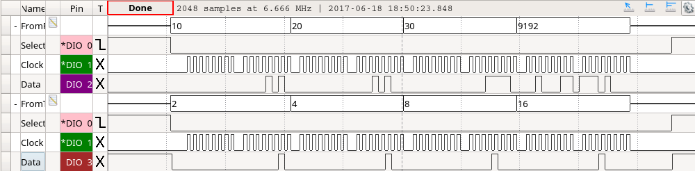
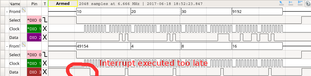
    In below figures you can see what happens with OK and too late interrupt response for Interrupt_SPI_enableTx:

    ON TIME INTERRUPT EXECUTION

  • TOO LATE INTERRUPT EXECUTION

  • Replaced by next post

  • Code to allow SPI slave select in motorware

    Based on Example_2806xExternalInterrupt.c from ControlSuite

    Use XINT1 for SPISTEA falling edge = start communication with that slave
    Use XINT2 for SPISTEA rising edge = stop communication with that slave

    Interrupt prioritization based on https://e2e.ti.com/support/microcontrollers/c2000/f/902/t/462460 and processors.wiki.ti.com/.../Interrupt_Nesting_on_C28x (next post from TI)

    All additional code is indicated by :
    - START :
     
    // ADDED CODE FOR 2 SPI SLAVES - BEGIN
    - END : // ADDED CODE FOR 2 SPI SLAVES - END

    For the digital isolator (hardware issue of DRV8301-69M kit), I post my comments in the other thread:
    e2e.ti.com/.../602564
    DRV8301-69M-KIT: DRV8301-69M-KIT: Running 2 SPI slaves HARDWARE problem

    Code in attached file

    CCS_2SPISlavesCode.docx

  • Tomas,

    The Interrupt priority on C2000 cannot be changed as it is HW based. However, you can implement some level of priority in SW. See the linked Wiki for more information. processors.wiki.ti.com/.../Interrupt_Nesting_on_C28x

    Side note: please refrain from posting entire files of code in the body of the post. It makes reading through a thread especially difficult. Use the "Use rich formatting" option and attach the file through the tools there. Thanks!

    Thanks,
    Mark
  • Thank you Mark! I moved the code in an attachment.

    The code in my previous post contains the translation of the link you sent to the MotorWare environment.
    It works fine apart from the optical isolator on DRV8301-69M-KIT, which I asked about in my direct communication.
    I will update my other post as soon as I get it working on the DRV8301-69M-KIT.

    BR,
    Tomas