Part Number: TMS320F28379D
Other Parts Discussed in Thread: C2000WARE, CONTROLSUITE
Hello everyone.
My goal is to write functions to read and write memory by SPI in ET1100. Below hardware configuration :
- TMS320F28379D: SPI-C muxed on 100, 101 and 102 GPIO, GPIO 103 as CS active low, 200MHz, LSPCLK 50 MHz.
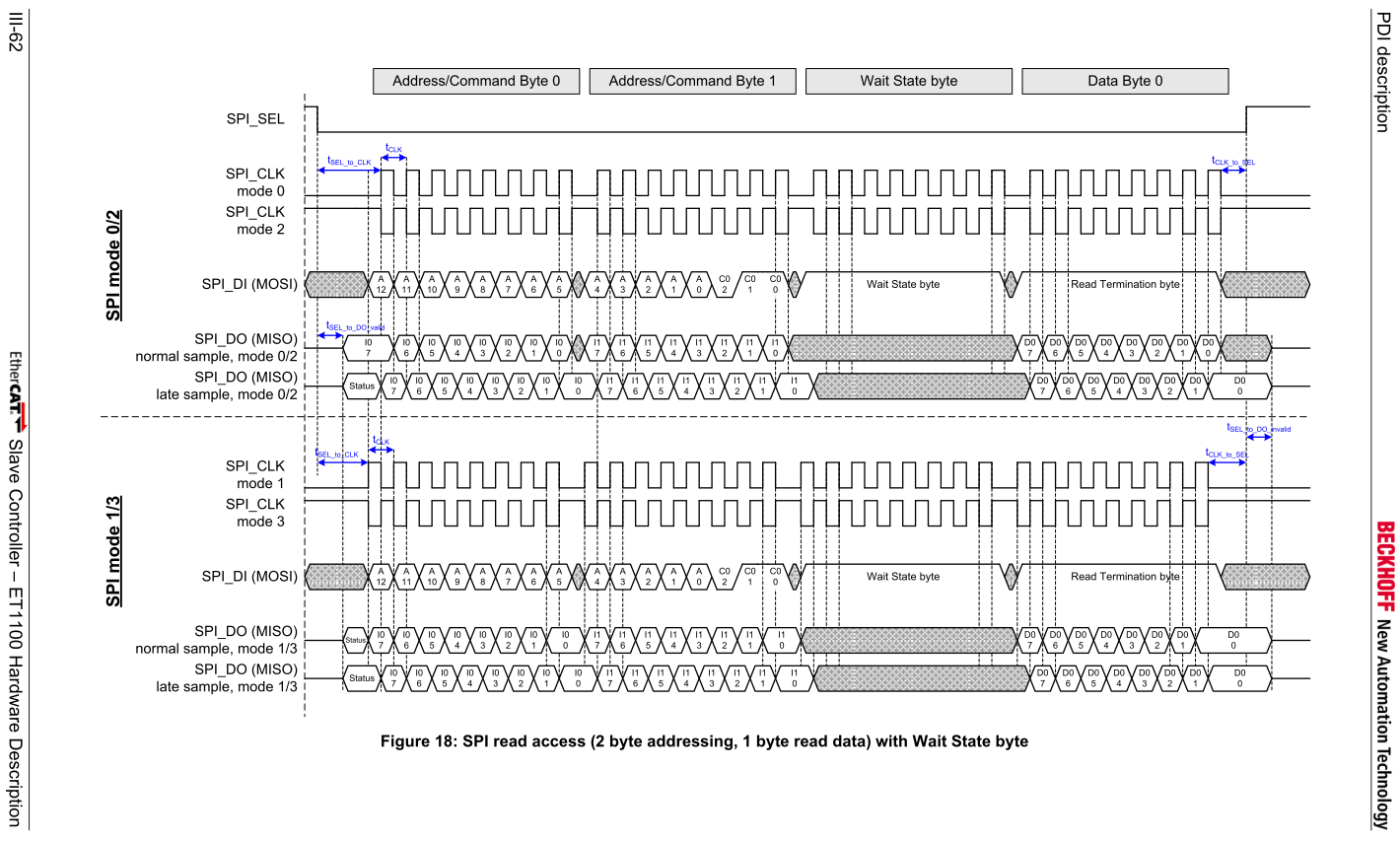
- ET1100: SPI mode 3, SPI sel polarity: active low, data output sample: normal.
I was trying to configure SPI step by step as it's desribed in 379D' manual. So below I placed my configuration functions:
void spi_fifo_init()
{
SpicRegs.SPIFFTX.all = 0xE040;
SpicRegs.SPIFFRX.all = 0x2044;
SpicRegs.SPIFFCT.all = 0x0;
InitSpiC();
}
void InitSpiC(void)
{
// Initialize SPI-C
// Enable master (0 == slave, 1 == master)
SpicRegs.SPICTL.bit.MASTER_SLAVE = 1;
// Set reset low before configuration changes
SpicRegs.SPICCR.bit.SPISWRESET = 0;
// Clock polarity (0 == rising, 1 == falling)
SpicRegs.SPICCR.bit.CLKPOLARITY = 0;
// Clock phase (0 == normal, 1 == delayed)
SpicRegs.SPICTL.bit.CLK_PHASE = 0;
// Set the baud rate
SpicRegs.SPIBRR.bit.SPI_BIT_RATE = 99;
// 8-bit character
SpicRegs.SPICCR.bit.SPICHAR = (8-1);
// Enable transmission (Talk)
SpicRegs.SPICTL.bit.TALK = 1;
// SPI interrupts are disabled
SpicRegs.SPICTL.bit.SPIINTENA = 0;
// Set FREE bit
// Halting on a breakpoint will not halt the SPI
SpicRegs.SPIPRI.bit.FREE = 1;
// Release the SPI from reset
SpicRegs.SPICCR.bit.SPISWRESET = 1;
}
void InitSpicGpio()
{
EALLOW;
// Enable internal pull-up for the selected pins
//GpioCtrlRegs.GPDPUD.bit.GPIO100 = 0; // Enable pull-up on GPIO100 (SPISIMOA)
GpioCtrlRegs.GPDDIR.bit.GPIO100 = 1; // mosi as output
//GpioCtrlRegs.GPDPUD.bit.GPIO101 = 0; // Enable pull-up on GPIO101 (SPISOMIA)
GpioCtrlRegs.GPDDIR.bit.GPIO101 = 0; // miso as output
GpioCtrlRegs.GPDPUD.bit.GPIO102 = 0; // Enable pull-up on GPIO102 (SPICLKA)
GpioCtrlRegs.GPDDIR.bit.GPIO102 = 1; // clk as output
GpioCtrlRegs.GPDDIR.bit.GPIO103 = 1; // cs as output
GpioCtrlRegs.GPDPUD.bit.GPIO103 = 0; // Enable pull-up on GPIO103 (SPISTEA)
//
// Set qualification for selected pins to asynch only
//
// This will select asynch (no qualification) for the selected pins.
// Comment out other unwanted lines.
//
GpioCtrlRegs.GPDQSEL1.bit.GPIO100 = 3; // Asynch input GPIO16 (SPISIMOA)
GpioCtrlRegs.GPDQSEL1.bit.GPIO101 = 3; // Asynch input GPIO17 (SPISOMIA)
GpioCtrlRegs.GPDQSEL1.bit.GPIO102 = 3; // Asynch input GPIO18 (SPICLKA)
GpioCtrlRegs.GPDQSEL1.bit.GPIO103 = 3; // Asynch input GPIO19 (SPISTEA)
//Configure SPI-C pins using GPIO regs
GpioCtrlRegs.GPDGMUX1.bit.GPIO100 = 1; // Configure GPIO16 as SPISIMOA
GpioCtrlRegs.GPDGMUX1.bit.GPIO101 = 1; // Configure GPIO17 as SPISOMIA
GpioCtrlRegs.GPDGMUX1.bit.GPIO102 = 1; // Configure GPIO18 as SPICLKA
GpioCtrlRegs.GPDGMUX1.bit.GPIO103 = 1; // Configure GPIO19 as SPISTEA
GpioCtrlRegs.GPDMUX1.bit.GPIO100 = 2; // Configure GPIO16 as SPISIMOA
GpioCtrlRegs.GPDMUX1.bit.GPIO101 = 2; // Configure GPIO17 as SPISOMIA
GpioCtrlRegs.GPDMUX1.bit.GPIO102 = 2; // Configure GPIO18 as SPICLKA
GpioCtrlRegs.GPDMUX1.bit.GPIO103 = 2; // Configure GPIO19 as SPISTEA
EDIS;
}
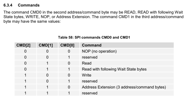
Could you tell me if my SPI configuration is genuine? I am not sure because I am trying to read 0x0 address from ET1100 (information about type of a device) and nothing is happening on txbuffer. Below my test code:
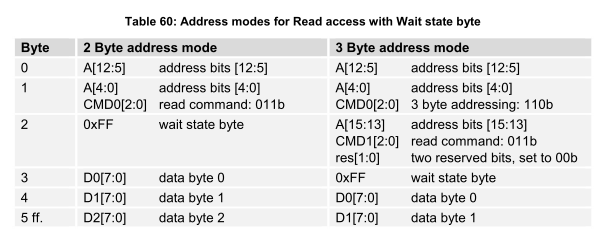
    unsigned int byte0 = 0x0;
    unsigned int byte1 = 0b00000011;
    unsigned int byte3 = 0xFF;

    GpioDataRegs.GPDCLEAR.bit.GPIO103 = 1;
    asm(" NOP");    //need 15ns delay
    asm(" NOP");
    asm(" NOP");
    asm(" NOP");

    SpicRegs.SPIDAT = (byte0 << 8); // sending first address byte
    while(SpicRegs.SPISTS.bit.BUFFULL_FLAG);

    SpicRegs.SPIDAT = (byte1 << 8); // sending second address byte
    while(SpicRegs.SPISTS.bit.BUFFULL_FLAG);

    SpicRegs.SPIDAT = (byte3 << 8); // sending wait state byte
    while(SpicRegs.SPISTS.bit.BUFFULL_FLAG);

    SpicRegs.SPIDAT = (byte3 << 8); // sending read termination byte
    while(SpicRegs.SPISTS.bit.BUFFULL_FLAG);
Any tip will be very appreciated.
ET1100 datasheet: download.beckhoff.com/.../ethercat_et1100_datasheet_v1i9.pdf