This thread has been locked.

If you have a related question, please click the "Ask a related question" button in the top right corner. The newly created question will be automatically linked to this question.

LAUNCHXL-F28069M: ADC Measurement

Part Number: LAUNCHXL-F28069M
Other Parts Discussed in Thread: CONTROLSUITE

Hi,

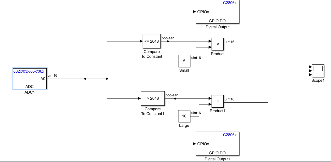
I made simple model in simulink to analyze ADC. When I connect ADCINA0 to GND and then ADCINA0 to 3.3V then it works perfectly with ADC goes from 0 to 4096 when I change GND to 3.3V . 

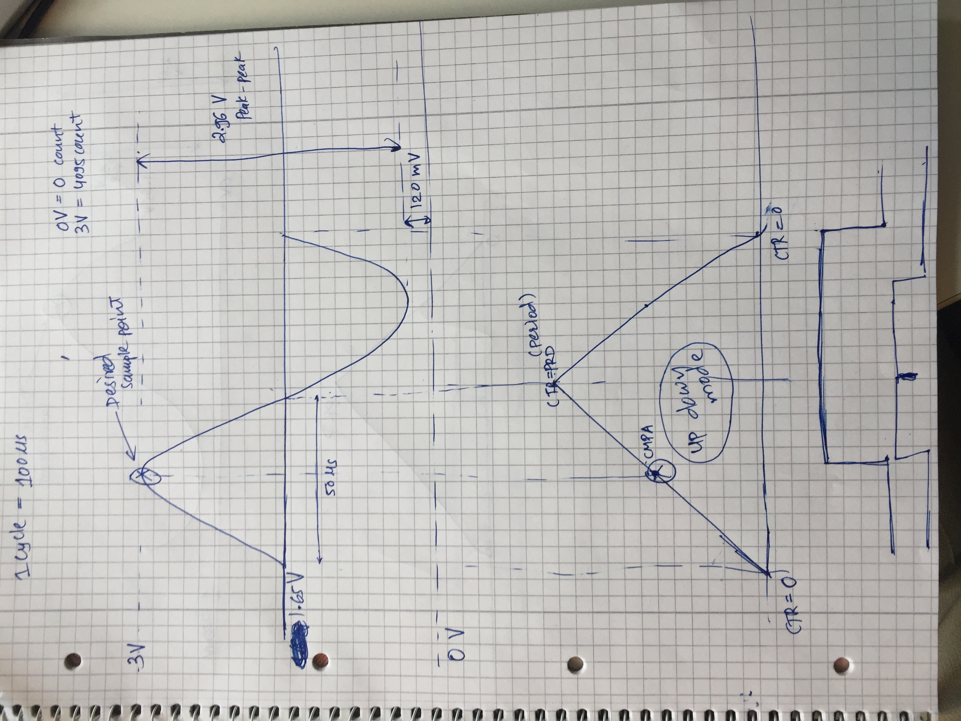
When I am floating the ADC pin then it gives me range of values which is not surprising. But when I connec this ADC to the sinwave(10khz,2.04P-P) which I took from my motor's sensor then it does nothing. 

I have set ADC sampling time to 10 times more the freq. of my wave (usually twice according to nyquist sampling theorem).

I have been stucked on this HW interface since LAUNCHXL-28069M doesnt have resolver interface and that is the reason I have to sort out this problem.

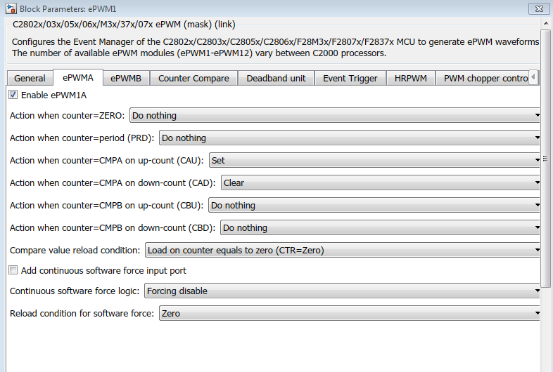
I have attached simulink model and set parameters. Can anyone help me how to use ADC?

thank you.

regards

Rahul

  • Hi,

    The following links are useful as a quick reference.

    http://e2e.ti.com/support/microcontrollers/c2000/f/171/t/635707

    https://e2e.ti.com/support/microcontrollers/c2000/f/171/t/146702

    From you mode, the ADC is software triggered. Could you consider a hardware trigger for the ADC and see if it improves the situation? The above to links also talk on the same line.

     To configure the ADC-SOC for hardware trigger please refer the example model we ship: ‘c2807x_2837xx_adcpwmasynctest_ert’

  •  Hi Venkatesh,

    I am using 2016b MATLAB.

    I want to sample data as shown in figure. Signal frequency is 10Khz and I am interested in only peak value of signal during each cycle.

    Basically I am getting data from my sensor (Resolver ) and as I change the shaft position of motor, The amplitude of signal will change accordingly and by reading the peak amplitudes I will get the posion(angle) of my shaft.

    I dont understand how to set some parameters. There are many trigger condition and which one to use? As the example that you have suggested and I did look at it and i did understand somewhat.  

    can you tell me how to get the desired point for each cycle and how to set parameters in ePWM if we use as it for trigger and what is the difference between difference trigger(software,ePWM,CPU). I have read documenatation but its too hard to understand.

    Thank you.

  • Hi,

    ADC can be triggered for conversion from on-chip peripherals like for example ePWM which does not require software intervention. We program the PWM module to generate the necessary trigger on specific ePWM events and this would happen internally without software intervention. On the contrary software trigger would need software to write to specific bits to generate the trigger. Is the sine wave always at 10KHZ of frequency? That way you can compute the time required to reach the mid point of the crest of the wave and accordingly program ePWM to generate the interrupt to ADC to sample at the given point of time. You may have to consider ADC conversion time and trigger a little ahead in time. For any question specific to MATLAB please contact
    www.mathworks.com/.../contact_us.html
  •   Hi,

    Thank you.

    But I am just intersted in one point. I have attched the scope from model. Both are the same. Just another is zoomed capture of first. can you tell me how to get that just one maximum point and save it to memory or so. Because with these samples, My angle is continuisly changing even if I am not changing shaft position and this is beacuse if it is taking all the point as input instead of just one peak.

    reagrds

    Rahul

  • Hi Lukhi,

    There is an example shipped from TI as part of controlSUITE on resolver interfacing.

    I found it at below path in my PC:

    C:\ti\controlSUITE\development_kits\TMDSRSLVR_v1.0

    HTH

  • Hi,

    I already read that example along ago but I could not find any information about how to set TBCLK, HSPCLKDIV value ?

    does anybody know if I want to sample analog singal which is of 10Khz frequency and the amplitude is varying from external input , I want to sample this signal with the help of ADC block triggered through ePWM module and how to set parameters like TBCLK and HSPCLKDIV and compare register value? I need only one sample per cycle and that is the peak of the half cycle.

    I have done calculation as shown in picture. where am I getting wrong? Plase help me to solve this issue. I am stuck on this for last 2 weeks.


    Thank you

    regards
    Rahul

  • Rahul,

          I am no resolver expert, but it seems that sampling at a higher rate would produce a better recreation of the sin/cos waveforms ultimately reducing jitter and increasing ENOB of the resulting position.

    None the less to answer your questions directly, TBCLK can be loaded to a predetermined value placed within TBPHS, this happens on a sync event. The sync event can come from multiple sources. These registers are typically used to establish a phase offset between PWMs as well as external events.

    HSPCLKDIV can be written to using the following  bit field structure "EPwm1Regs.TBCTL.bit.HSPCLKDIV = 0". Assuming your waveform diagram is drawn correctly and that all signals are always perfectly aligned you can configure SOCA or SOCB's trigger source as CMPA. This will trigger a conversion whenever the CMPA event occurs.

    Look at the PWM section of the TRM, it will provide further details on all of these things.

    Regards,

    Cody