This thread has been locked.
If you have a related question, please click the "Ask a related question" button in the top right corner. The newly created question will be automatically linked to this question.
Hi
I am trying to port my program that runs well in a RAM configuration to a Flash configuration
So I exclude from compilation the
f28069F_ram_lnk.cmd file and replace it with
F28069M.cmd
I still have the
F2806x_Headers_nonBIOS.cmd
in my project for the Peripheral registers
In the beginning of the code I have the
#ifdef _FLASH // Copy time critical code and Flash setup code to RAM // The RamfuncsLoadStart, RamfuncsLoadEnd, and RamfuncsRunStart // symbols are created by the linker. Refer to the linker files. memCopy((uint16_t *)&RamfuncsLoadStart,(uint16_t *)&RamfuncsLoadEnd,(uint16_t *)&RamfuncsRunStart);
now, It compiles and runs (with the debugger)
do I have to replace the lib
IQmath_fpu32.lib
with 2806x_IQmath_BootROMSymbols_fpu32.lib
?
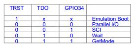
but if I unplug the USB then replug it, it doesn't boot, What is the configuration of the JP BOOT ? J1 J2 J3
Can I still use GUI with FLASH activated ?
Any clue appart from reading the
Running_from_Flash_spra958l.pdf
Thanks
As the boot mode table in the schematic of LaunchXL-F28069M, Set S1-3 to OFF, S1-1 and S1-2 to ON if you want to run the code in Flash without connecting the JTAG emulator. Only need to set S1-3 to ON if you want to run the code under emulation boot mode, the mode can support running code in both Flash and RAM. More detailed description about boot mode can be found in reference manual of F2806x.
Thanks, but I found the doc of the LAUNCHXL-F28069M Overview sprui11.pdf
completely unclear:
5.3 Boot Mode Selection
The LaunchPad's F28069M device includes a boot ROM that performs some basic start-up checks and
allows for the device to boot in many different ways. Most users will either want to perform an emulation
boot or a boot to flash (if they are running the application standalone). S1 has been provided to allow
users to easily configure the pins that the bootROM checks to make this decision. The switches on S1
correspond to:
Switch Function
1 GPIO34
2 GPIO37
3 TRSTn
Keep in mind that the debugger does not connect if the device is not in the emulation boot mode (TRST
switch in the up position). More information about boot mode selection can be found in the Boot ROM
section of the TMS320x2806x Piccolo Technical Reference Guide (SPRUH18).
-----------------------------
this post explain better
https://e2e.ti.com/support/microcontrollers/c2000/f/171/p/489498/1768299#1768299
but
I run the Example_2806xFlash
Without the need to change S1, I can start debugging or start the prog. (wthout debugging) simply by connection power USB
Whereas my program, doesn't boot alone when connecting the power. I can only run it with CCS. Though I see he is flashing memory in (Flash mode)