Other Parts Discussed in Thread: CONTROLSUITE, AMC1306E25, TMDSDOCK28379D, AMC1306EVM, C2000WARE, AMC1306M25
Tool/software: Code Composer Studio
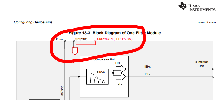
I'm trying to master the SDFM of TI F28377D chip, temporarily running a single-core application (core 2 is not used). My current setup is based on the sdfm_pwm_sync_cpu01 example provided with controlSUITE, with the following adaptations:
- There are only SD1_D1, SD1_D2, SD1_C1 and SD1_C2 connected (GPIOs 16 to 19). Filters 2 and
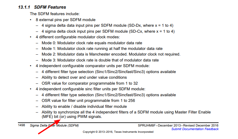
- The data is in Manchester encoding, therefore Sdfm_configureInputCtrl() receives MODE_2 as input.
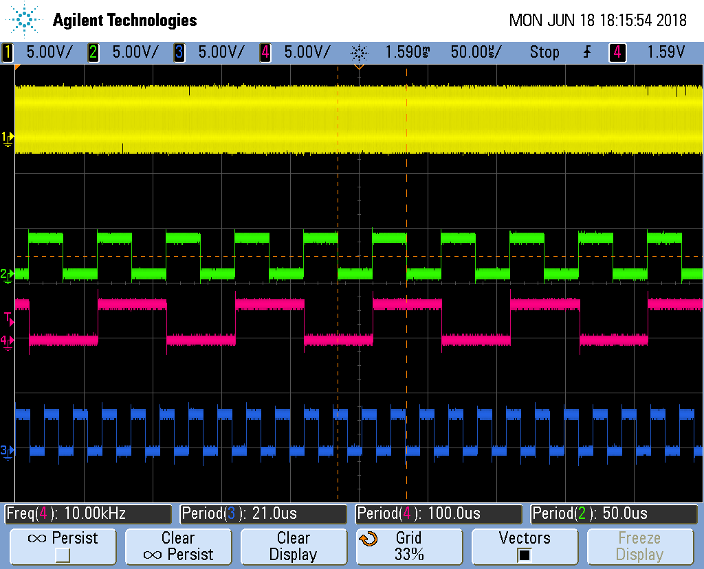
- The clock, even if not required by the Manchester encoding, is supplied from one of the eCAP modules.
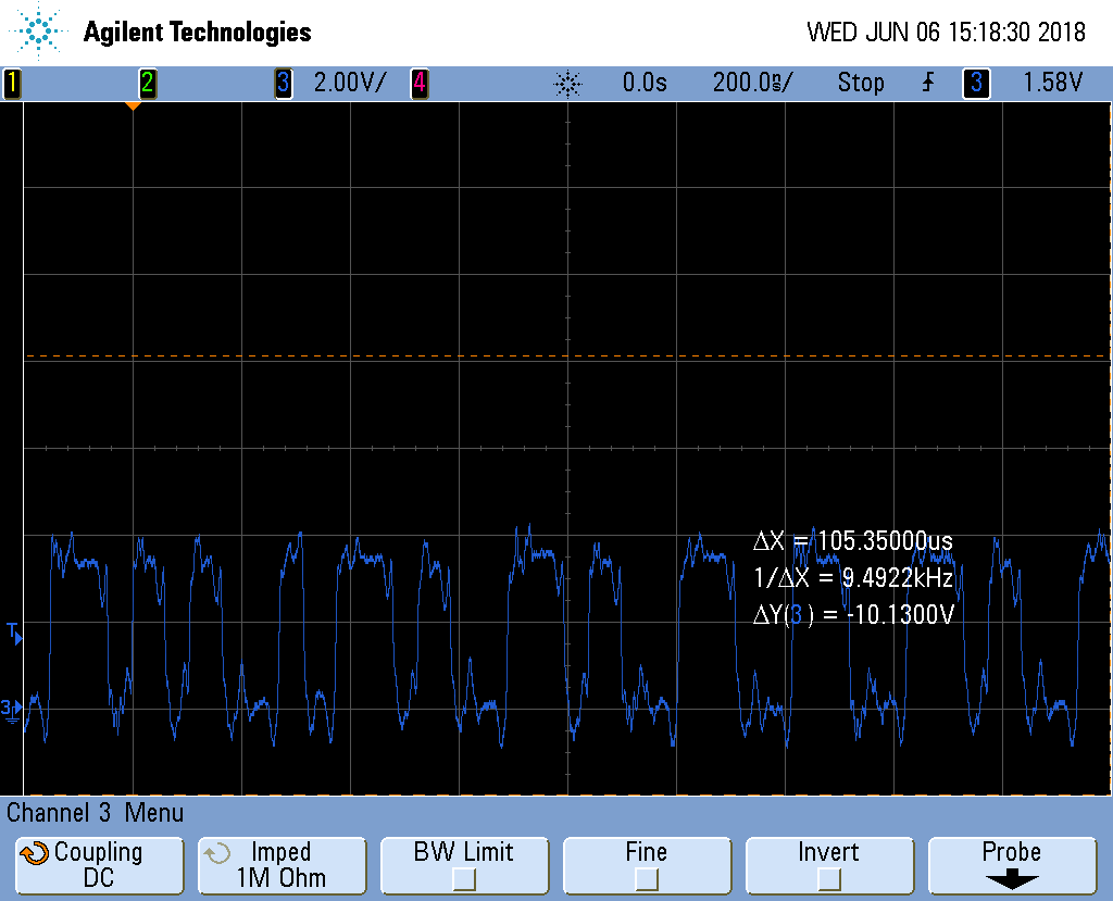
I have connected voltage source to the setup to emulate some kind of input for SD, and I do see some Manchester-encoded data on the corresponding DSP leg. However, running this example (or, to that matter, any sdfm example), I finish reading of the first result in the Sdfm1_ISR routine and fall to the following trap:
__interrupt void Sdfm1_ISR(void)
{
    uint32_t sdfmReadFlagRegister = 0;
    static uint16_t loopCounter1 = 0;

    //
    // Read SDFM flag register (SDIFLG)
    //
    sdfmReadFlagRegister = Sdfm_readFlagRegister(gPeripheralNumber);

    if(loopCounter1 <= MAX_SAMPLES)
    {
        //
        // Read each SDFM filter output and store it in respective filter
        // result array
        //
        Filter1_Result[loopCounter1] = SDFM1_READ_FILTER1_DATA_16BIT;
        Filter2_Result[loopCounter1] = SDFM1_READ_FILTER2_DATA_16BIT;
        Filter3_Result[loopCounter1] = SDFM1_READ_FILTER3_DATA_16BIT;
        Filter4_Result[loopCounter1++] = SDFM1_READ_FILTER4_DATA_16BIT;

        //
        // Clear SDFM flag register
        //
        Sdfm_clearFlagRegister(gPeripheralNumber,sdfmReadFlagRegister);
        sdfmReadFlagRegister = Sdfm_readFlagRegister(gPeripheralNumber);
⇐ Here sdfmReadFlagRegister is 2147484416
        if(sdfmReadFlagRegister != 0x0)
        {
            ESTOP0;
⇐ And, sure enough, I finish here
        }
    }
I tried disabling fiters 2, 3 and 4, to no success. What are the ways to continue from here.


