This thread has been locked.

If you have a related question, please click the "Ask a related question" button in the top right corner. The newly created question will be automatically linked to this question.

CCS/TMDSSOLARUINVKIT: C2000 micro inverter questions

Part Number: TMDSSOLARUINVKIT

Tool/software: Code Composer Studio

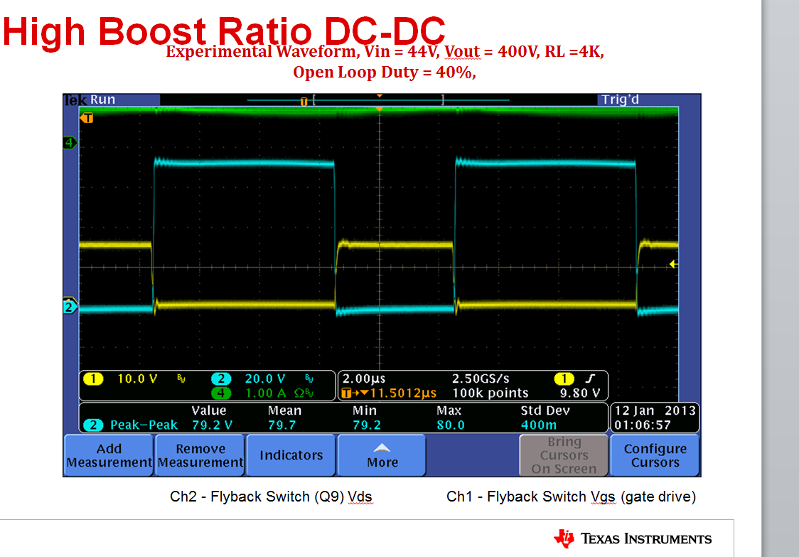
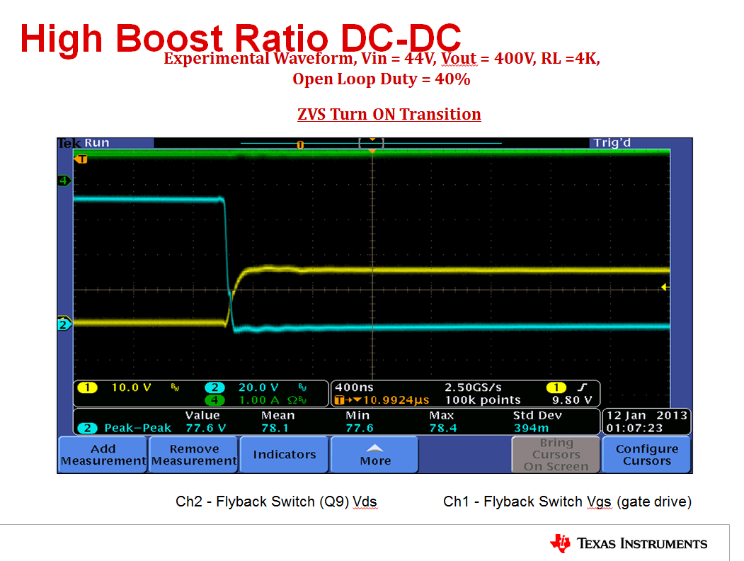
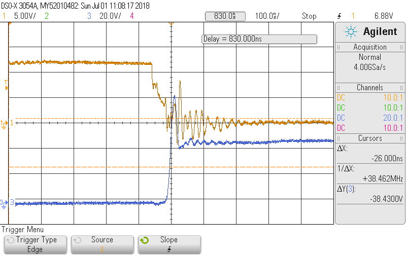
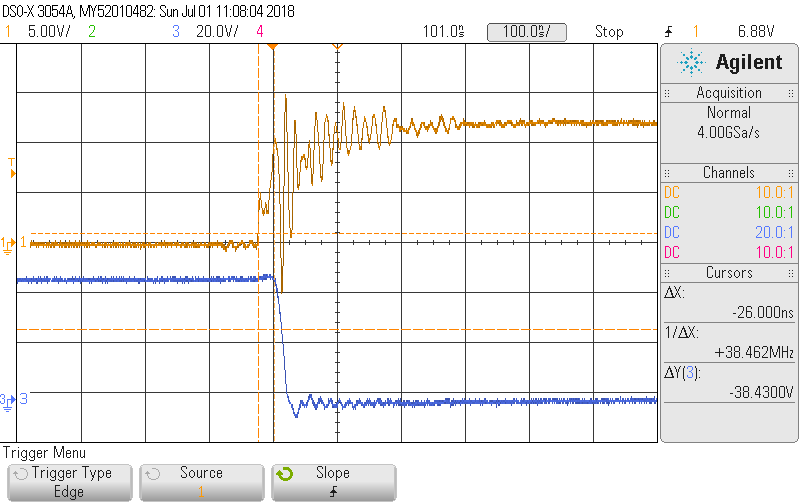
When I tested TMDSSOLARUINVKIT under 270W , the case temperature of Q9 reached to 100 degree Celsius and raised continuously so I shut it down immediately. Therefore, I checked Vgs and Vds of Q9, and found it was not soft-switching. Supposedly that the active clamp Flyback works with ZVS(zero-voltage-switching) to increase conversion efficiency. May I know what can I do under this circumstance? Thanks.

  • Hm.. well there are some aspects of soft switching because of the clamped flyback. However there is still conduction loss. I think you may be able to change heatsink etc. or use a different FET.
  • Well. Refer to test results on page 52 of "tidu405bUG", the "Pin" reaches 316.87W so I suppose that the clamped flyback on TMDSSOLARUINVKIT is capable to handle 270W; otherwise, the efficiency would never be up to 90%. Is soft-switching implemented with of clamped flyback in TMDSSOLARUINVKIT?
  • From what i know and understand it,

    1. Energy stored in T1 mag inductance (Lm) transferred to C2, fly-back action.
    2. T1 leakage inductance (Lp, Ls) energy transferred to Cac during fly-back operation
    3. Np:Ns = 5:27, Vin = 30V, Duty = 61.5%, Vout = 416V
    4. Lowest switch volt stress compared to other fly-back topologies.
    5. Resonance between leakage ind and diode (D1, D2) parasitic caps causes reduced
    circulating current in primary clamp circuit. Reduces conduction losses in clamp circuit .
    6. Resonance between leakage ind and diode parasitic caps causes additional boost action.
    7. Primary switch (both FETs) ZVS turn on

    Are you able to read the FET part number of the device used on Flyback?
  • Hi Manish,
    I am using the development kit "TMDSSOLARUINVKIT" with 110Vrms output, and Vin=30V, Duty=46.3%, Vbus=275V; however, I can't see ZVS when I checked Vgs and Vds of Q9. The part number of FET is "IRFB4227" which are implemented on the development kit by the way.
  •  Hm , I have asked my manager to look at this as he designed the HW, but he is  out of office for a couple of weeks.

    In the meanwhile can you provide some waveforms for the Vgs and Vds ? I am attaching our experimental result above done good 5 + years ago... 

    you also may want to check in open loop first.. 

  • As per the spec the max load with 120Vac input is about 140W. So you must be overloading it with 270W.

    2.4 Solar Micro Inverter Electrical Specifications
    Following lists the key highlights of the micro inverter.
     Panel Voltage: 28V (Min) to 45V (Max)
     DC bus voltage: 400V (max)
     Output Power: 280W @ 220Vac, 140W @ 110Vac
     DC-DC & DC-AC combined efficiency ~92% at 50% rated load, THD~5%

    Shamim

  • It looks like with the 319W test at 220 Vrms we may have been streching the coverter spec , I will recommend you to test with the spec provided above only.
  • Hi Shamin,
    It is my understanding that "TMDSSOLARUINVKIT" has two stages; they are, an active clamp flyback converter with a secondary voltage multiplier and a DC-AC inverter, and they are separated. Whatever the DC-AC inverter output (280W or 140W), the active clamp flyback converter should be capable convert 280W output power. The only difference is that higher output voltage will introduce lower output current on inverter side. Am I right?
  • Hi Manish,
    Well. Even though I tested output power at 280W, there is still thermal issue at Q9.
  • Hi Manish,

      The yellow and blue colors are Vgs and Vds of Q9, respectively.I also tested it in open loop (build 1).

  • The Vgs voltage under open loop has lot of ringing. I suspect there is something wrong with the circuit. Our open loop test waveform does not show this ringing. At this point I would say you replace the FET and the gate drive circuit. If that does not work then you have to get a replacement for the board.

    The flyback DC/DC stage should allow 280W power at least at 45V input, regardless of Inverter out voltage (110V/220V).

    Shamim

  • Hi Shamim,
    Actually I have replaced Q9 several times since it burned out frequently. Let me check the Vgs voltage under open loop again and see if there is something wrong with my measurement. Thanks.